16 signal flow and lake processing – Lab.gruppen PLM 20000Q User Manual
Page 22
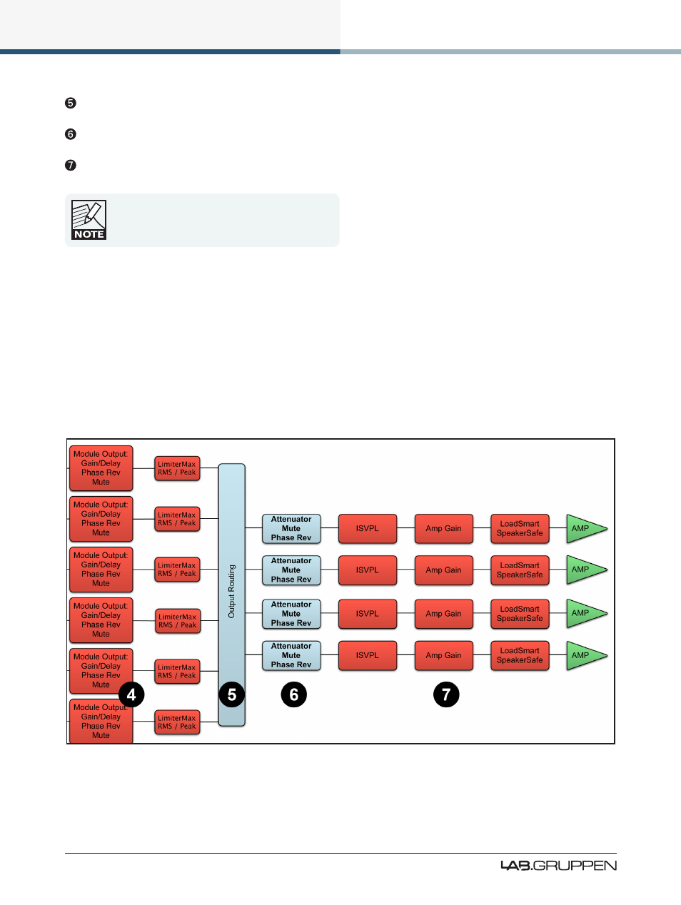
16
Signal Flow and Lake Processing
PLM Series Quick Start and Field Reference Guide Rev 1.3.5
Output Router Stage
- Output ON/OFF routing connections
Attenuation Stage
- Power output channel mute and attenuation settings
Amp Gain Stage
- Amplifier gain control
If the required audio signal is not passing correctly,
verify the connection, mute and gain settings at all
seven stages.
5.1.1 Power Output Section: Limiting and Sensitivity
The Current Peak Limiter (CPL) dynamically limits the drive to the power stage based on three parameters:
sensed output current level, feedback from the output stage, and sensed voltage clip from the ISVPL. This
ensures that power output is maintained within the design limits of the PLM.
The adjustable Inter-Sample Voltage Peak Limiter (ISVPL) sets the PLM’s maximum output voltage and
therefore also the maximum output power. The ISVPL setting is made via MENU > MODULE > LIMITERS
> ISVPL, and can also be set from the Lake Controller software.
Figure 5-2: Signal Flow Diagram (4-channel PLM Part 2)