Hobbywing XERUN SCT PRO User Manual
Page 3
USER MANUAL OF XERUN-SCT PRO ESC VER: HW-SM507ENG-20121102 Page 3 of 3
【PROGRAM THE ESC】
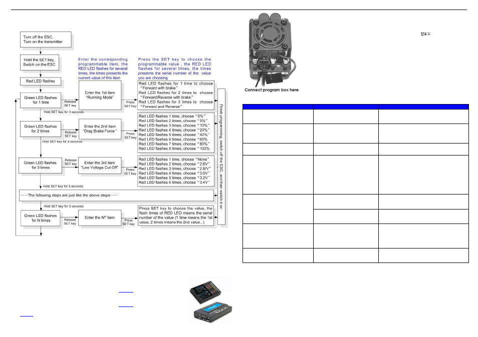
1. Program the ESC with the SET button on the ESC
Please refer to the following instructions.
Note:
►
In the program process, the motor will emit
“Beep” tone at the same time when the LED is flashing.
►
If the
“N” is bigger than the number “5”, we use a long time flash and long “Beep---” tone to represent “5”, so it is
easy to identify the items of the big number.
For example, if the LED flashes as the following:
“A long time flash + a short time flash” (Motor sounds “Beep---Beep”) = the No. 6 item
“A long time flash + 2 short time flash” (Motor sounds “Beep---BeepBeep”) = the No. 7 item
“A long time flash + 3 short time flash” (Motor sounds “Beep---BeepBeepBeep”) = the No. 8 item
And so on.
2. Program the ESC with the LED program box (Optional equipment )
Please refer to the user manual of LED program box.
(Note3)
3. Program the ESC with the advanced LCD program box (Optional equipment )
Please refer to the user manual of LCD program box.
(Note3)
Note3:
The control wire of the ESC (for connecting receiver) CANNOT be used to
connect with the LED Program Box or LCD Program Box to program this ESC.
You must use the 3 pin port between the soldering terminal #A and #B.
Normally, this 3 pin port is used to connect cooling fan, when programming the
ESC, please unplug the cooling fan connector.
Please also make sure that the 3 pin program port of the ESC must be connected
with the Program Box through the port
marked with “
” in parallel, the
cross connection is not correct.
【TROUBLE SHOOTING】
【POWER SYSTEM SUGGESTIONS】
Trouble
Possible Reason
Solution
After power on, motor doesn’t work,
and the cooling fan doesn
’t work
The
connections
between
battery pack and ESC are not
correct
Check the power connections
Replace the connectors
After power on, motor can’t work,
but emits
“beep-beep-, beep-beep-”
alert tone. (Every “beep-beep-” has
a time interval of 1 second )
Input voltage is abnormal, too
high or too low
Check the voltage of the battery pack
After power on, red LED always
lights, the motor doesn
’t work
Throttle signal is abnormal
Plug the control wire into the throttle channel
of the receiver correctly.
The motor runs in the opposite
direction when it is accelerated
1)The wire connections between
ESC and the motor are not
correct
2)The chassis is different from
the popular design
1) For sensorless motor: Swap any two wire
connections between the ESC and the motor.
Or use the following method.
2) For sensored motor: Please check the wire
connections, they must be A-A, B-B, C-C
respectively. If the connections are correct,
please
change
the
“Motor
Rotation
”
programmable item to
“CW(Clockwise)”
The motor suddenly stops running
while in working state
The throttle signal is lost
Check the transmitter and the receiver
Check the signal wire from the throttle channel
of your receiver
The ESC has entered the Low
Voltage Protection Mode or
Over-heat Protection Mode
Red LED flashing means Low Voltage. Green
LED flashing means Over-heat
When accelerating quickly, the
motor stops or trembles
1) The battery has a bad
discharge performance
2) Gear ratio is too aggressive
3) The
“Start Mode (Punch)” of
the ESC is too aggressive
1) Use a better battery
2) Use lower KV motor or softer gear ratio
3) Set the
“Start Mode (Punch)” to a softer
value
When the throttle stick is in the
neutral range, the red LED and the
green LED flashes synchronously
Over current protection, motor
demagnetization, or motor is
over load
1) Reduce the load (Use softer gear ratio or
reduce the input voltage)
2) Change the motor