HITEC HFP-25 User Manual
Page 4
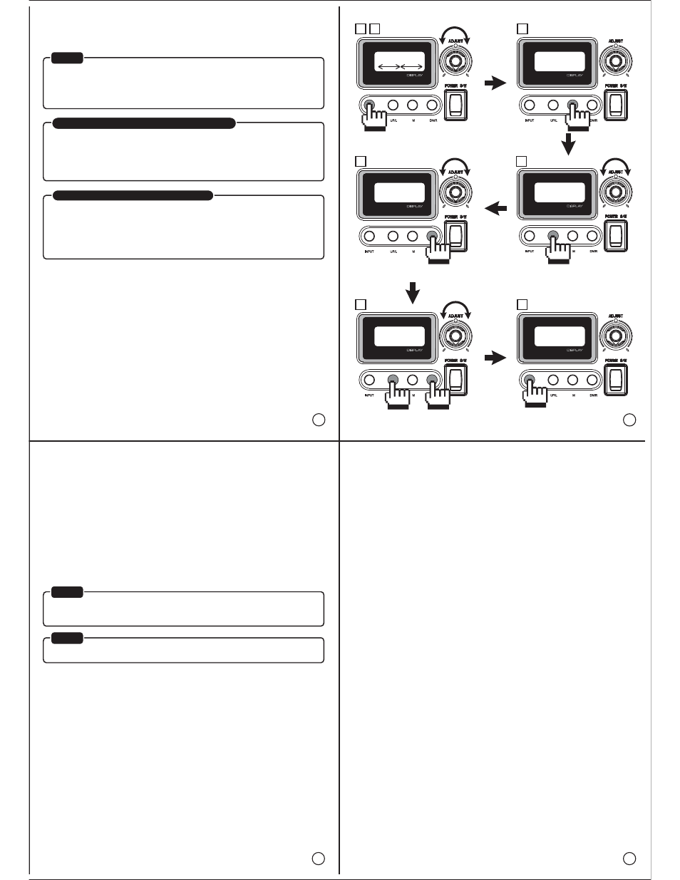
8. EPAneuFS (EPA, Neutral and Fail-safe):
This feature allows your servo’s End Positions, Center position and Fail-safe position.
To set the End positions, Center position and Fail-safe position,
9. Transmitter Signal Pulse:
See the pulse the receiver is supplying to the servo.
a. Push the INPUT button to enter. The programmer will wait until you have set the adjustable
knob to its center.
The display shows you or when the knob is out of the center.
The HFP-25 will search for the current settings and the servo movement will be controlled
with the adjustable knob.
b. To set the center position, use the adjustable knob to set the servo to the desired position
c. Press the M button, “center” should appear on the screen.
!! IMPORTANT: If you change the center position, the each end position must be re-adjusted. !!
d. To set the left end position turn the adjust knob to the left and when the desired position is
reached press the UP/L button.
e. To set the right end position, turn the adjustable knob to the left and when the desired
position is reached, press the DN/R button.
f. Then to set the fail-safe position, turn the adjustable knob to the desired position and push
the UP/R and DN/R buttons simultaneously.
* To turn the fail-safe function “on” or “off” within the servos programming, see step 5.
g. Push INPUT to save and exit.
a. Push the INPUT button to view the pulse from the transmitter.
b. Move the stick associated with the channel the programmer is plugged into to see the pulse
range.
c. Press INPUT to exit.
10. Voltage:
View the voltage that is being supplied to the servo from the receiver.
* For this procedure the programmer must be plugged into any receiver channel.
a. Turn the transmitter on and then turn on the receiver switch.
NOTE: there must be a 4.8 or 6V battery plugged into the receiver to power it.
b. Press the INPUT button and the voltage will appear. The lowest voltage level will be shown
on the display.
c. When you press the M button, you will see the actual voltage level.
The voltage level will drop down when you have servos connected to the receiver are moving.
You also can connect one servo to HFP-25 and drive it with the knob.
d. Press the INPUT button to exit.
11. S-Test Auto (Servo Test Auto):
Test the servo movement automatically.
a. Press the INPUT button to enter.
b. Turn the adjustable knob to actuate the servo manually.
c. To test the end positions press the UP/R button to actuate the servo automatically.
The normal parameters for this are 2100μs to 900μs.
d. Use the adjustable knob to set the sweep speed.
e. Press the INPUT button to stop.
f. To test the operation of the servo potentiometer, press M. The programmer will sweep the
output pulse from 2100μs to 900μs and back. The servo will drive slowly from one end
position to another.
Observe the servo horn, if it moves smooth, things are fine. If the movement is jerky or
stutters, the servo potentiometer could be dirty or defective.
g. Use the adjustable knob to set the sweep speed.
h. Press the INPUT button to stop.
i. To test the resolution of the servo and see the difference in dead band values between other
servos, press the DN/R button.
j. Turn the adjustable knob to set the jitter value from 0μs -31μs.
k. Press INPUT twice to exit.
12. S-Test Manual (Servo Test Manual):
Test the servos movement manually.
a. Press the INPUT button to enter.
b. Turn the adjustable knob to actuate the servo manually.
c. To test the left end position, press the UP/R button. The value should be 900μs.
d. Press INPUT to exit.
e. To test the center position, press the M button. The value should be 1500μs.
f. Press INPUT to exit.
g. To test the right end position, press the DN/R button. The value should be 2100μs.
h. Press INPUT to exit.
i. To test the fail-safe position, push UP/R and DN/R simultaneously.
The value should be 0μs (no pulse to the servo). After a second, the servo should drive into
the fail-safe position, you enabled in step 5.
j. Press INPUT to exit.
k. To exit and back to the main menu, press INPUT again.
* For this procedure the programmer must be plugged into the receiver channel that you want
to test.
*NOTE
*NOTE
there must be a 4.8 or 6V battery plugged into the receiver to power it.
*NOTE
Test function of HFP-25
Ŗ 6TCPUOKVVGT 5KIPCN 2WNUG
Ŗ 5GTXQ 6GUV #WVQ
Ŗ 8QNVCIG
Ŗ 5GTXQ 6GUV /CPWCN
13
14
15
16
Section Two Transmitter and Servo Test Section
The following are test functions and can apply to any model of servo or
transmitter.
EPAneuFS
xxx
EPAneuFS
xxx
EPAneuFS
xxx
EPAneuFS
xxx
EPAneuFS
EPAneuFS
xxx
a
b
* For purposes of calibration in respect to Hitec transmitters the values are -225 one
direction from center and +225 the other direction.
With the value of +100 or -100 being 40 degrees of servo travel from center and
corresponding to the value of 100% travel on a Hitec radio.
So as to avoid overdriving your servo past its physical limits of travel, you cannot set a
servo center position more than 15 degrees from its factory preset center position.
If the center position is set more than 15 degrees from the factory default center position,
the EPA function will not work.
For servo’s proper operation, setup sequence is the one most important thing for
EPA setup.
You must keep the following sequence:
Center(neutral) position -> “M” -> left end position -> “UP/R” -> right end position ->
“DN/R”.
c
e
d
f
g
! Note on the EPA (End Position Adjustment) Procedure!
! Important Note on the EPA set up procedure!