HITEC Spectra 2.4 Module User Manual
Page 2
Press and hold the link button on the receiver and turn on the power.
- Low Battery Warning function is only for your reference. The actual battery level could be
the Low Battery Warning function.
- When the 2.4GHz system and HV servos are used together, we strongly recommend using
fully-charged, large capacity battery packs and you must constantly monitor the battery status.
Warning
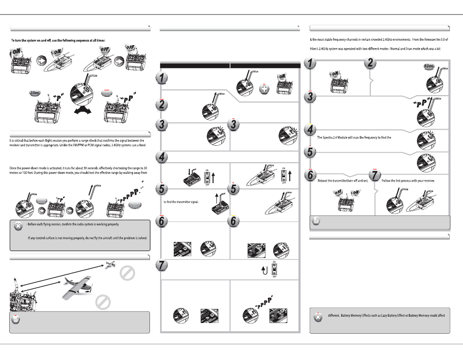
General Use Guidelines
Scanning Function
Warning
Range Check Function
General Use Guidelines
shorter, stubby transmitter antenna known as a rubber duck antenna. So, the traditional method of range
check, lowering the transmitter antenna, is not applicable.
The Hitec 2.4GHz System uses a power-down mode to reduce the transmitter signal strength.
the secured aircraft and carrying the transmitter to a minimum distance of approx. 30 meters or 100 feet.
How to use Power-Down
- Before the engine or motor is started, turn on the system as explained above.
Make sure all the servos and control surfaces are working properly.
- If you are unable to accomplish a successful range check of 30 meters or 100 feet,
DO NOT ATTEMPT TO FLY.
The SmartScan is a unique function of Hitec’s AFHSS 2.4GHz technology to provide the user with the cleanest
the Spectra 2.4 module, you can utilize “Scan” function more conveniently without complexity (previously,
complicated to use). The following explains how to use the Scanning function properly.
Link (ID-Setup or Bind)
Press and hold the button on the module,
and turn on the transmitter.
Range Check Mode
Scanning
cleanest and most stable frequency in the concerned area.
(The BLUE LED on the module will blink during the scanning)
When the scan is completed,
the BLUE LED on the module stops blinking and glows steady.
Release the link button when you hear two continuous beeps.
Turn on the transmitter.
Both RED and BLUE LEDs will blink rapidly
Release the link button when the
RED LED on the receiver glows steady.
When the link is completed, the BLUE LED on the
module will blink while the BLUE LED on the receiver
glows steady.
When they are turned on again, the RED LED on the
module(or radio) and the BLUE LED on the receiver
will glow steady.
When they are turned on again, you will hear a
continuous beep sound. Both the RED LEDs on the
module and receiver will glow steady
in normal status.
Release the link button.
Check if the BLUE LED is blinking.
If the RED LED is blinking, press
the link button for 2 sec., so
that the LED changes to BLUE.
C
C
C
C
C
C
C
C
C
Release the link button.
Wh
Wh
Wh
Wh
Wh
Wh
Wh
Wh
Wh
Wh
Wh
Wh
Wh
Wh
Wh
Wh
Wh
W
W
W
W
W
W
W
W
W
W
W
W
W
W
W
W
When the link is completed, the BLUE LED on the
module will blink while the RED LED on the module
glows steady. For the receiver, both BLUE & RED LEDs
will glow steady.
Link Guidelines
Too Close: Less than 50Cm(18in)
Too F a r : Mo re than 5M(15ft)
- Link must be done within 15ft.(5m) of the transmitter and receiver.
- Transmitter and receiver need to be at least 18in.(50cm) from each other to link properly.
Note
Telemetry System
The Hitec Spectra 2.4GHz module and Optima series of receivers feature full telemetry capabilities (except for
the Optima 6) and include a Low Receiver Battery Warning as a basic function.
I. Basic Function: Low On-Board Battery Warning - for All Optima Receivers
When the Optima series of receivers are powered up, it will automatically detect the battery voltage level and
recognize between 4-cell or 5-cell NiMH and NiCd batteries (4-cell < 5.8V <5-cell).
If a 2-cell LiPo battery is being used, you can customize the battery warning level by using our HPP-22
program.
- When the battery level is safe (4-cell > 4.5V, 5-cell > 5.6V), no changes will appear to the LED lights.
- When the battery level is low (4-cell < 4.5V, 5-cell < 5.6V), the BLUE LED glows constantly and the RED LED
blinks fast. Three continuous beeps from the module serve as a low receiver battery warning. Upon hearing
the beeps, we advise you to land at once.
II. Optional Functions: GPS, FUEL, TEMP, O-RPM, M-RPM, VOLT, Amp Sensors - Applicable for Optima 7 & 9 Only
- More devices will be available in the future. Check the Hitec website at www.hitecrcd.com for more
up-to-date information.
- After Scanning, you need to do the link process again for all your receivers as receivers also need
new frequency hopping codes from the Spectra 2.4 module.
Note
2.4GHz 6 Channel
Aircraft Recei
ver
2.4GHz 6 Channel
Aircraft Receiv
er
Channel
R eceiver
Channel
R eceiver
Check if the RED LED is blinking.
If the BLUE LED is blinking,
press the link button for 2 sec.,
so that the LED changes to RED.
C
C
C
W
W
W
W
W
W
W
W
W
W
W
W
W
W
W
W
W
W
W
W
W
W
W
W
W
W
W
W
W
W
W
W
W
W
W
W
W
W
W
W
W
W
To save the setting, please reboot both the transmitter and receiver.
Non-telemetry RXs (MINIMA & MICRO Series)
Telemetry RXs (OPTIMA Series)
Your Hitec AFHSS system uses a communication protocol that links and binds the Hitec 2.4GHz receiver to
your transmitter. Once the receiver and module are “bound,” no other transmitter can interfere with your
receiver during its operation. In the case of multiple model memory transmitters, you can bind as many Hitec
2.4GHz receivers to your transmitter, one per model memory as necessary.
Each module and receiver set is paired at the factory for your convenience.
Use one of the following binding methods to bind additional Hitec 2.4GHz receivers to your transmitter.
Press and hold the link button on
the Spectra 2.4 Module for about 6 sec.
6Sec.
6Sec.
3Sec.
3Sec.
90Sec.