Pilatuspc6 – HITEC Pilatus PC-6 Turbo Porter User Manual
Page 7
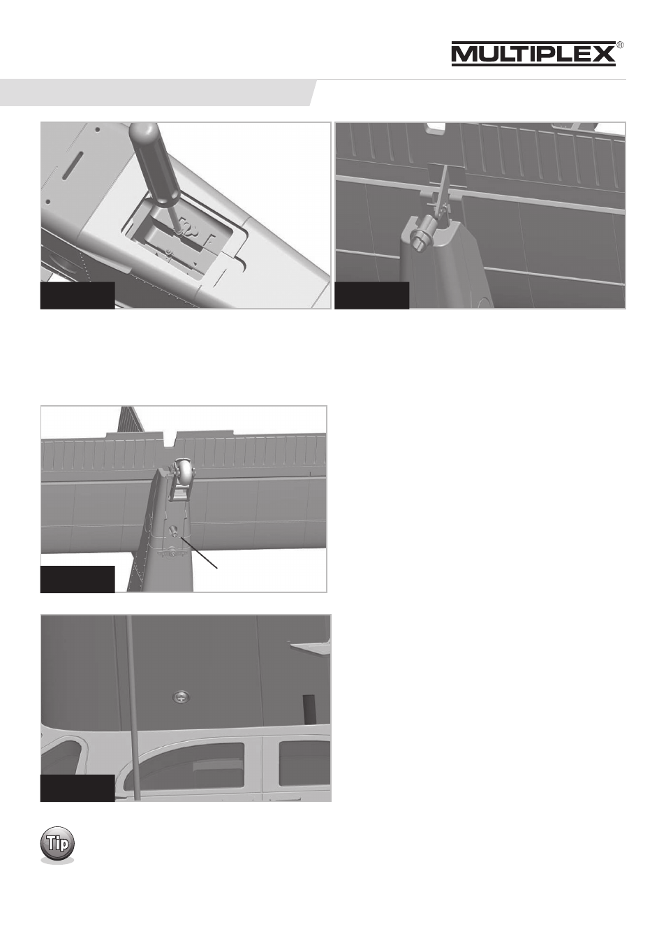
Step 2: attaching the elevator assembly
2a: Remove the servo access hatch from the underside of
the fuselage and set it aside. Locate the elevator servo (L.H.
servo, as seen from the tail) and loosen the screw on the
connector barrel so that you slide the pushrod easily.
2b: Slide the elevator assembly (Part # 11) half-way into
the slot in the fuselage, using a pair of needle nose pliers,
connect the elevator pushrod to the elevator horn, working
from the right-hand side as shown in the illustration.
Step 3: fitting the Wings
3a: Remove the battery hatch on top of the fuselage to gain
an unobstructed view of the interior of the fuselage. Slide the
CFRP wing joiner (Part #15) into one of the wing panel (Part #s
13 & 14) Thread the servo connectors through the opening in
the fuselage before pushing the wing up against the fuselage.
Repeat the procedure with the other wing Fit the retaining
screws in the holes in the underside of both wings close to the
fuselage, and tighten them firmly. The clamping screws hold
the wing joiner - and with it the wings - securely against the
fuselage.
ASSEMBLY INSTRUCTIONS (cont.)
Step 2a
Step 3a
Step 2c
Step 2b
24
2c: With the pushrod connected, you can slide the tail
plane fully into the slot, making sure that the other end of
the pushrod is still located in the connector barrel at the
servo. Secure the elevator assembly using the M4 x 45 mm
(part # 24) Philips head screw inserted from the underside.
Tighten the screw only lightly, otherwise you could dam-
age the foam pieces. Switch your radio control system on,
and set the elevator to the neutral position. Apply a drop of
thread-lock fluid to the M2 screw in the swivel connector to
prevent the elevator pushrod working loose, then tighten
the clamping screw firmly. The servo access hatch can now
be reattached.
Wrap tape around the two servo connectors to make it easier to handle them.
7
PilatusPC6