Parts, Three steps of installation, Scope – Grandview GPCM-D User Manual
Page 2
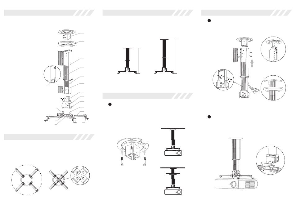
Parts
GPCM-D is combined by GPCM and GPD
GPCM Main Bar Overview
1-1 Fixation
1-2 Top Cap
2-1 Main Bar
2-2 Subsidiary Bar
2-3 Ornament Board of Main Bar
2-4 Ornament Board of Subsidiary Bar
2-5 Ornament Cap of Main Bar
GPD Adjusting Overview
3-1 Adjuster
3-2 Hanging Button
3-3 Horizontal Adjusting
Hole
4-1 Installation Bracket
4-2 Installation Arm
4-3 Adjustable Screw
4-4 Sliding Installation
Button
4-5 Installation Base
4-6 Vertical Adjusting
Button
Install the fixation on the ceiling (screws of accessory① )
as figure 1. GPCM-D can be installed to the concrete-
roof with ceiling or without ceiling,such as figure 2 and
figure 3.
1
3
Scope for installation (Installation hole of projector):
Maximum scope for installation:360mm diameter
Minimum scope for installation:50mm diameter
Note: Connect the installation arms to the projector conversely for different installation
holes of projector.
Maximum diameter: 360mm
Connect the GPCM Main Bar Overview to the fixation
(screws of accessory ②).Store the power wire, and then
fasten the front and back screws of main bar. Finally,
install the ornament board of main bar as figure 4.
2
Three steps of installation
Scope for installation (H is the distance between ceiling and projector)
The H of GPCM-D3040 is 300mm~400mm
The H of GPCM-D4060 is 400mm~600mm
GPCM-D3040
GPCM-D4060
Scope
Accessories:
① M6x25 Tapping Screw (3sets)
② M5x10 Philips Screw/
Washer/Spring Washer (4sets)
③ M4x8 Socket Cap Screw (6pcs)
④ M5x8 Philips Screw (2pcs)
⑤ M3x8 Philips Screw (4pcs)
⑥ M4x8 Philips Screw (4pcs)
⑦ M5x8 Philips Screw (4pcs)
1-1
1-2
2-1
2-4
2-3
3-1
3-3
2-2
3-2
2-5
figure 4
Fasten the front
and back screws
of main bar.
Minimum diameter: 50mm
Scope
Hang the installation bracket (projecter has been
installed) to the adjuster as figure 5. And then put in the
screws (accessory ④),but do not faster.
Install the
top cap
Connect main bar
and adjuster (screws
of accessory ③)
figure 5
figure 1
figure 2
figure 3
Three steps of installation
4-1
4-2
4-3
4-4
4-5
4-6
H
H