Grandview LF-MIRCII(Recessed-Ceiling Series) User Manual
Page 6
10
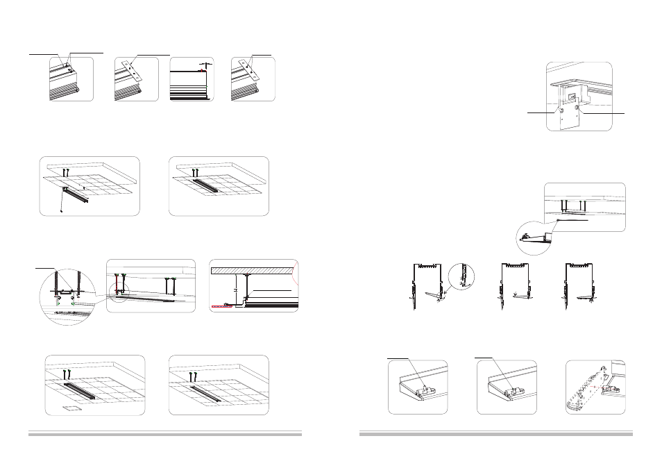
Note: the upward instruction shows us installation of external control system, if the users want to add other control
systems, please follow the steps as below:
1)Loose the screws of power box and take out the power box (because
the power cord has a limit, please do not
draw it strongly). Then loose two rubber screws again, and remove the
end cap (please ensure the power line is
fixed), step 3 can be follow.
2)Insert the control system signal line to corresponding output (figure 11),
and take out the signal line from control
system signal line exit (figure 19).
3)Reinstall the end cap after completed control system and fasten the
two rubber screws then reinstall the power box and fasten two screws
according to step 8.
10. Install the front baffle as following steps
1) Extend the screen and keep the rear baffle opening
2) Disconnect the power of screen,and then install the front baffle
3)Please ensure the security lock is unlocked (figure 22).
4)Install the front bafle (figure 23)
5)Unlock the security lock of baffle (
、
), insert the
plug of security to a hole of end cap (figure 26), if the baffle can not
move up that please align baffle with ceiling board.
6)Connect the power after installation
figure 24
figure 25
Figure21
Signal Line Exit
Figure22
Figure24
Figure25
Figure26
Figure23
5.Please stay the screen in the opposite direction, and fix the left and right hanging board on the screen using
M6 screw and nut (figure 12).
6. Install the whole screen on the hanging bracket (figure 13-14)
7. Fix the screen using M12 nut (figure 15), then adjust the security distance to H (the distance between concrete roof and ceiling
surface) using adjusting screw. Loose the M12 nut and fix the whole screen, and then connect the power (figure 16).
5
Figure13
figure 12
Figure15
Figure14
1)
in the groove of casing.
Stay the M6 allen screw
2) Install the hanging
board
3) Please ensure the
distance between edge
of hanging board and the
edge of casing is 5mm.
4) Fasten the hanging board
using M6 nut, and install other
hanging board at the same way.
Hanging Board
Casing Groove
M6 Allen Screw
M6 Nut
8. Cut the separated ceiling board in a suitable size, which can fill in the size of space as screen (figure 17-18).
Figure18
Figure17
Figure16
5.0
Unlocked
Locked
M12 Screw (4pcs)
M12 Nut
Power Line
1) Insert the baffle to top groove.
2) Stay flat the baffle,
and clip it to low groove.
3) Press the baffle slightly
and align it with ceiling board.
Top Groove
Low Groove
Ensure two faces
are the same level