Installation instructions, Invisa® htr 7000 owner’s manual, Installation into existing walls or ceilings – GoldenEar Invisa HTR 7000 User Manual
Page 8
GoldenEar Technology
►
Invisa HTR 7000 Manual
Invisa® HTR 7000 Owner’s Manual
Installation Instructions
Installation of your new Invisa
®
HTR 7000 speakers requires use of tools such as a drill, screwdriver, saws and possibly
other power tools. The installer should have knowledge of all applicable building and/or fi re codes. Care must be
taken to ensure the area behind the wall or ceiling where you plan to install the speakers is clear of obstructions.
When cutting the hole in and running wires through walls and/or ceilings proper care must be taken to avoid
electrical, water, gas and/or HVAC pipes and the corresponding risks to your safety and risk of damage to property.
If you are not comfortable with the above and/or performing the following installation procedures we strongly
suggest having a professional contractor install your speakers (see your GoldenEar Technology Dealer).
Tools Required:
• Pencil
• Drywall saw, Keyhole saw, utility knife or other material-appropriate cutting tool for wall material
• Phillips Head Screwdriver
• Power drill with appropriate bit (optional, for starting wall cut)
Installation Into Existing Walls or Ceilings
For new construction (pre-drywall), use our custom rough-in brackets, sold separately.
NOTE: You must fi rst install appropriate gauge and type speaker
wires. For best sound quality, the use of high quality speaker cable
is essential.
1. Make sure the wall material can support the weight of
the speakers you plan to install (see specifi cations
page
for
weights).
2. Make sure the location selected is free of studs, electrical
wiring, water or gas pipes, etc. Prior to installing, hold the
speaker in your selected location to make sure it is clear
of
any
obstacles.
PLEASE NOTE: Your cutout must be at
least 2" (50mm) from adjoining walls/ceiling, internal
studs, and any pipes.
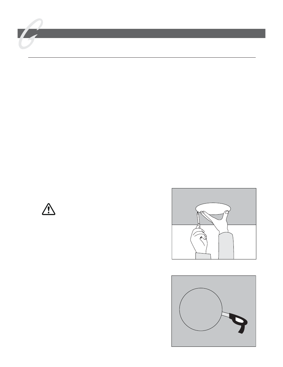
3. Place the included mounting template onto the wall or
ceiling in your preferred location. Use the pencil
to trace around the template (Figure 1).
4. Carefully cut a hole with the appropriate cutting tool
along the pencil trace as follows: Start the hole by
drilling a hole inside of the pencil line (place drill bit just
inside the line). Use this hole to insert the cutting tool
and begin cutting — be careful not to cut outside the
template line! (Figure 2).
8
Use only cable that is rated for in-wall use
(UL Standard CL2, CL3 and CM, CSA standard FT4).
Figure 1
Figure 2