0 installation, Installation diagram – Go Power! GP-TS User Manual
Page 3
Owner’s Manual | Go Power! – Transfer Switch Kit
2
Carmanah Technologies Corp. © 2011
Last revised: August 2011
3.0 Installation
1. Ensure the shore power plug is not connected to shore power and batteries are disconnected.
2. Connect the RV shore power cord to Go Power! Transfer Switch input: wires are labeled “Shore Hot”
and “Shore Neutral”. Connect ground wire to provided ground bonding block.
3. Connect transfer switch output to AC power panel. (Use terminals labeled “AC Panel”).
4. Plug supplied inverter power cord into inverter. (With inverter power switch “off” or disconnect inverter
from the battery.)
5. Plug Go Power! Battery Charger into transfer switch female outlet and connect to batteries. (When
using a stock converter charger, remove the AC connections from the breaker panel and add a male
plug to connect with the transfer switch female outlet.)
6. Disable converter when using a stand-alone charger.
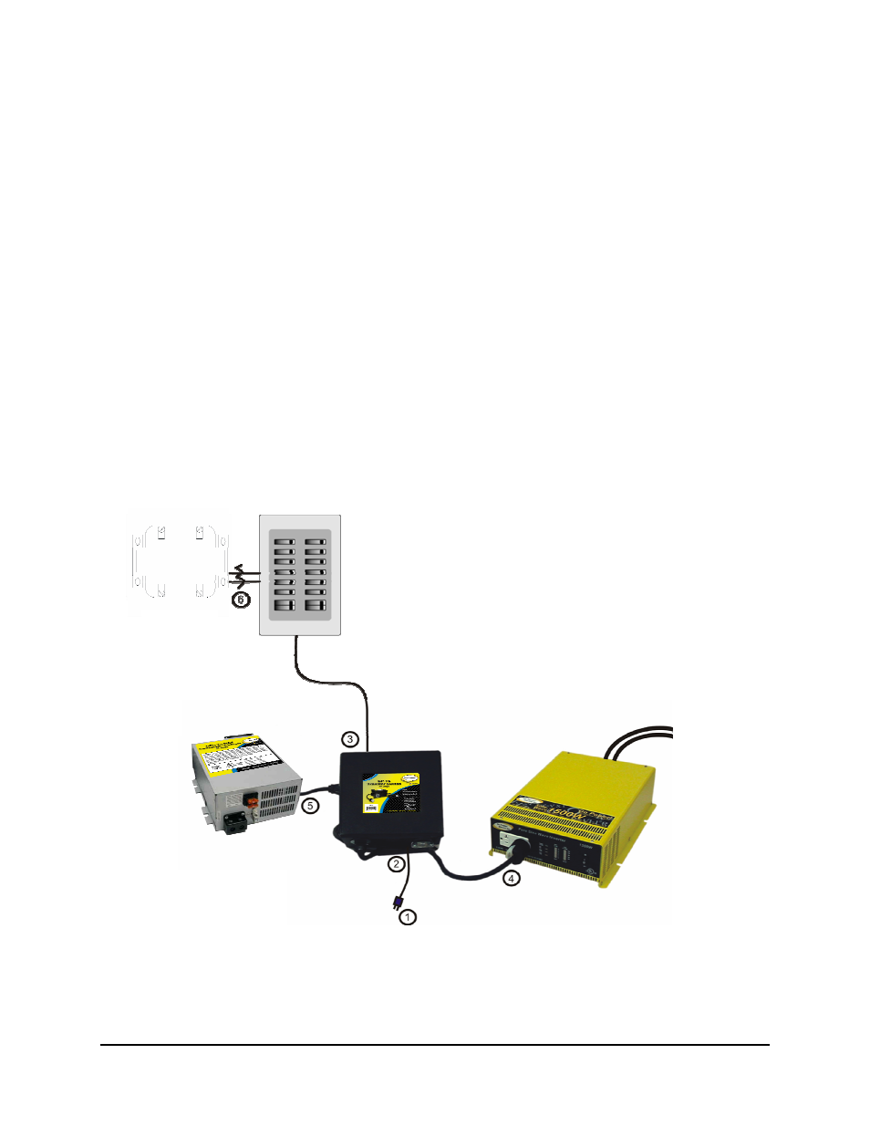
3.1
Installation Diagram
AC Panel
Converter
Go Power! Battery Charger
or
Stock converter charger
Go Power! Inverter
Go Power!
Transfer Switch
Disconnect Shore
Power
To Batteries