Operation – Go Power! GP-300 User Manual
Page 6
Go Power! Modified Sine Wave Inverter
Owner’s Manual
Go Power! Modified Sine Wave Inverter
Owner’s Manual
7
6
4.2 Hook-up and testing
To hook-up the inverter please follow these guidelines:
* Important: If you are using the battery interconnect cables supplied with
this inverter then please read the following. The interconnect leads with the
alligator clip style DC connections already include a 35 amp fuse. This will be fine for
any application 300 watts and under. The DC car lighter input cable includes a 15 Amp
fuse. Most North American car lighters are rated between 10 - 15 Amps DC and are
fused in the automobile fuse box. Please consult your automobile owners manual for
the fuse rating of your lighter It is recommended that you DO NOT exceed a load of 100
watts for a 10 Amp fuse and 140 Watts for a 15 amp fuse when using your car lighter
to power this inverter.
1. Unpack and inspect your Go Power! Inverter, check to see that the power switch
is in the OFF position.
2. DC Lighter Plug - Insert DC input plug into any 12V DC car lighter receptacle and
proceed to step 6
3. Interconnect Cables -Attach the DC inverter cables to the DC power input
terminals on the rear panel of the power inverter. The (+) terminal is positive and (-)
terminal is negative. Connect the cables to the terminals by placing the lug connec
tor at the base of the terminal and tightening the terminal screw or nut. Clamp the
wires securely and ensure connections are tight.
Caution! A reverse polarity connection will blow a fuse in the inverter and
may permanently damage the inverter. Damage caused by reverse polarity
connection is not covered by our warranty.
4. First connect the cable from the negative terminal of the inverter to the negative
terminal of the battery. Make a secure connection.
Caution! Loose connections result in excessive voltage drop and may
cause overheated wires and melted insulation. Ensure connections are
tight.
5. Before proceeding further, carefully check that the cable you have just con
nected is going from the negative terminal of inverter to the negative terminal of
the power source (battery).
6. Connect the cable from the positive terminal of inverter to the positive terminal of
the battery. Make a secure connection. Check your polarity.
7. Set the power switch to the ON position. Check that the power LED is ON, and if
not, check your battery bank and the connections to the inverter.
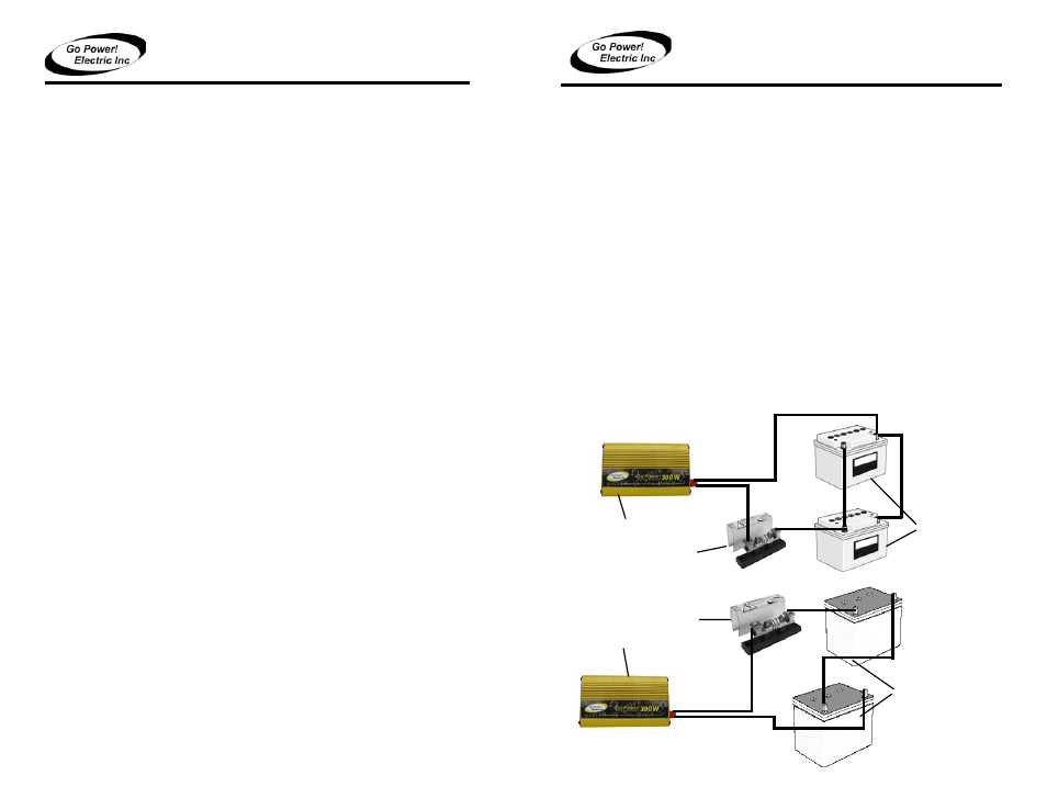
*Installation using two 12 volt batteries.
Warning! You may observe a spark when you make this connection since
current may flow to charge capacitors in the power inverter. Do not make
this connection in the presence of flammable fumes, as explosion or fire
may result.
8. Set the power inverter switch to the OFF position. The power LED light may blink
and go dim. The internal alarm may sound momentarily. This is normal. Plug the test
load into the AC receptacle on the front panel of the inverter.
9. Set the power inverter switch to the ON position and turn the test load on; the
inverter should supply power to the load. If you plan to measure the output
voltage of the inverter, a true rms meter must be used for accurate readings.
4.3 Cables
Cables are included with the unit. If user supplied cables are preferred, please use 6 ft or
less of #10 Cable with a 35 Amp fuse. Install the inverter fuse into the positive lead. Fuse
should be located within 12” of battery. Ensure all connections are tight and secure.
4.4 Inverter fuse example
• GP-300 - 110 amp fuse with 10’ #4 cable
5. Operation
To operate the power inverter, turn it on using the ON/OFF switch on the front panel. The
6 V Batteries
GP Inverter
GP Fuse
*Installation using two 6 volt batteries.
d) Safe - Do not install the inverter in the same compartment as batteries or in any
compartment capable of igniting flammable liquids such as gasoline.
e) Inverter should be located within 10 feet of the batteries.
12 V Batteries
GP Fuse
GP Inverter