5 boiler installation – Glow-worm Micron 30FF User Manual
Page 16
16
221910F
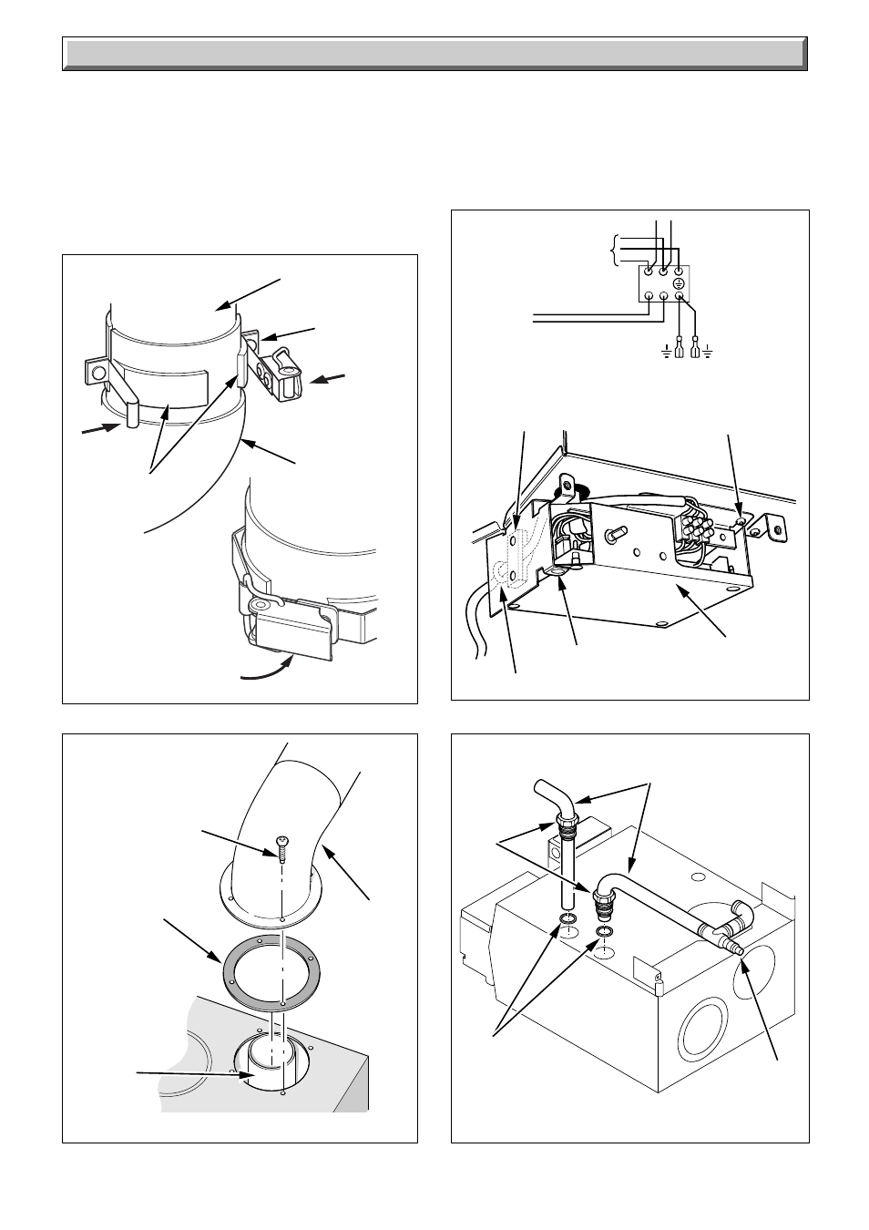
MAINS
SUPPLY
230V~50Hz
BLOCK
CONNECTOR
bl
L
S
N
g/y
g/y
g/y
br
b
bl b
b
Diagram 5.10
5 Boiler Installation
SECURING
SCREW
12384
CONTROL
BOX
5.8 Pump Connection
The pump must be connected to the external controls.
5.9 Testing
Checks to ensure electrical safety must be carried out by a
competent person.
After installation of the system, preliminary electrical system
checks as below should be carried out:
Diagram 5.9
TOP
TURRET
6793
GASKET
SCREWS
(4)
TOP TURRET
FLUE OUTLET
FLUE
DUCT
EXTENSION
HINGE PIN
7224
Diagram 5.8
CABLE
CLAMP
GROMMET
FLUE DUCT
EXTENSION
RETAINING
CLAMP
FAN ELBOW
PRESS
PRESS
PRESS
CLASP
1. Test insulation resistance to earth.
2. Test earth continuity and short circuit of all cables.
3. Test the polarity of the mains.
The installer is requested to advise and give guidance to the
user of the controls scheme used with the boiler.
Fit the casing.
Diagram 5.11
7333
TAIL PIPE
TUBING
NUT
AIR VENT
RETURN
FLOW
RUBBER
WASHER
FAN ELBOW
CLAMPING
SURFACE
- 12-38hxi Range (44 pages)
- 18-30sxi Range (48 pages)
- 23c (44 pages)
- 24-38CXI Range (52 pages)
- 30ci Plus (56 pages)
- BBU 45/4 (32 pages)
- BBU 54/4 (32 pages)
- Betacom C (68 pages)
- Betacom2 (8 pages)
- Betacom2 (20 pages)
- Betacom2 (56 pages)
- Black Beauty 4 (20 pages)
- Chatsworth 4 (24 pages)
- Clearly Heat Recovery (20 pages)
- Clearly Heat Recovery (32 pages)
- Clearly Heat Pumps Envirosorb3 (28 pages)
- Clearly Heat Pumps Envirosorb2 (44 pages)
- Clearly Heat Pumps 7kW (44 pages)
- Clearly Heat Pumps 5kW (28 pages)
- Clearly Heat Pump 5kW (16 pages)
- Clearly Heat Pump 5 kW (32 pages)
- Clearly Heat Pump - Buffer Vessel (10 pages)
- Clearly Heat Pumps - Standalone Module System (40 pages)
- Clearly Heat Pumps - Standalone System (28 pages)
- Clearly Hybrid - Universal Module (20 pages)
- Clearly Hybrid - Universal Module System (36 pages)
- Clearly Hybrid - Compact Hydraulic Module (12 pages)
- Clearly Hybrid - Compact System (36 pages)
- Clearly Hybrid - Compact Hydraulic Module HB (16 pages)
- Clearly Hybrid - Back-up Module System (40 pages)
- Clearly Solar System Hydraulics (28 pages)
- Clearly Solar System (28 pages)
- Clearly Solar Controller (28 pages)
- Clearly Solar Horizontal On-Roof Collector (16 pages)
- Clearly Solar Vertical On-Roof Collector (16 pages)
- Clearly Solar Cylinders (32 pages)
- Clearly Solar - A-Frame (28 pages)
- Clearly Solar Horizontal In-Roof Collector (32 pages)
- Clearly Solar Vertical In-Roof Collector (44 pages)
- Clearly Solar Collector Container (8 pages)
- Climapro 1 (12 pages)
- Climapro2 RF (16 pages)
- Climapro2 RF (24 pages)
- Climapro2 RF (36 pages)
- Climapro2 RF (32 pages)