10 fault finding – Glow-worm 56-2 Back Boiler User Manual
Page 21
21
221781A
10 Fault Finding
Diagram 10.3
THERMOCOUPLE
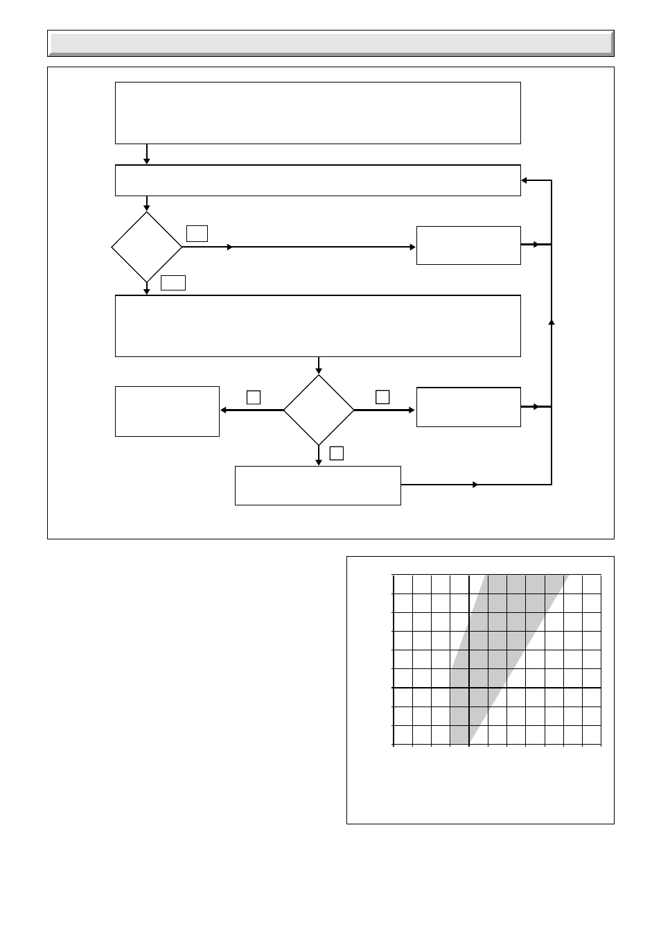
FAULT FINDING CHART
Diagram 10.4
DIAGNOSIS GRAPH FOR BOILER
THERMOCOUPLE CIRCUIT
1429
Closed Circuit Voltage (millivolts)
Open Circuit Voltage (millivolts)
0
2
4
6
8
10 12 14 16 18 20 22
9
11
13
15
17
19
21
23
25
27
A
B
C
Disconnect appliance thermocouple from the gas valve. Check that all connections are
clean and in good condition. Fit test meter interrupter into the magnet unit. Fit appliance
thermocouple into the test meter interrupter. Check that the flue blockage safety device
sensing filter is clean, if not remove / clean and replace.
NO
YES
Hold down control knob on gas valve. Ignite pilot burner and allow thermocouple to attain
operating temperature. Measure the OPEN CIRCUIT voltage.
Is
voltage
greater
than
15mV?
Faulty thermocouple.
Replace.
Note the open circuit reading then measure the CLOSED CIRCUIT voltage. Note this voltage.
Referring to the diagnosis graph, mark the open circuit voltage on the VERTICAL axis,
and the closed circuit voltage on the HORIZONTAL axis. Note the point where these
two values intersect on the graph.
THERMOCOUPLE
CIRCUIT IS
SATISFACTORY
In
which
area of the
graph is the
intersect
Faulty thermocouple.
Replace.
Faulty magnet unit in gas valve.
Replace .
B
A
C
6131