0 installation – ENMET Venturi Gas Sampler User Manual
Page 4
Venturi Module
ENMET Corporation
2
2.0 Installation
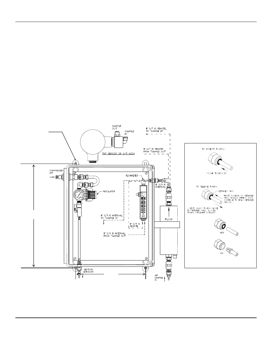
See Figure 1 for mounting Dimensions. Dimensions are in inches.
2.1 Installation Sample Draw Module
1.
Mount the sample draw module at a convenient location; use the four mounting holes provided. See Figure 1.
C
AUTION
:
Do not exceed 120
PSI
to inlet to the venturi pump.
2.
Supply compressed air to the inlet of the venturi pump, located at the upper left side. The inlet fitting is a Hansen 1000 quick
release pneumatic connector. If a different connector is desired, remove and discard the Hansen fitting; the replacement
fitting must have ¼ NPT male threads.
3.
The sensor assembly can be mounted on the sample draw assembly plate, or it can be located within six feet of the plate. If
necessary, connect the sample line from the bottom port of the flowmeter to the output side of the sensor assembly.
C
AUTION
:
If reactive gasses such as CL2, HCL, NH3 or others are being sampled, make sure to use appropriate sample tubing
material. Teflon lined vinyl tubing is acceptable for most applications.
4.
Supply tubing from the sensor input fitting to the sample point. The sample must never include liquid.
5.
Set the regulator between 8 and 18
PSI
.
6.
Set the flowmeter between 3.0 and 8.0 cc/min x 100.
Figure 1: Mounting Dimensions
Mounting Feet
4 places
14.94
Inches
10.00
Inches
Detail of Adapter Fitting