2 internal electronic circuitry, Isa-ral-m, isa-rah-m enmet corporation 3, 110 vac power supply outside of control unit – ENMET ISA-RAL-M User Manual
Page 7: N.c.= normally closed n.o.= normally open
ISA-RAL-M, ISA-RAH-M
ENMET Corporation
3
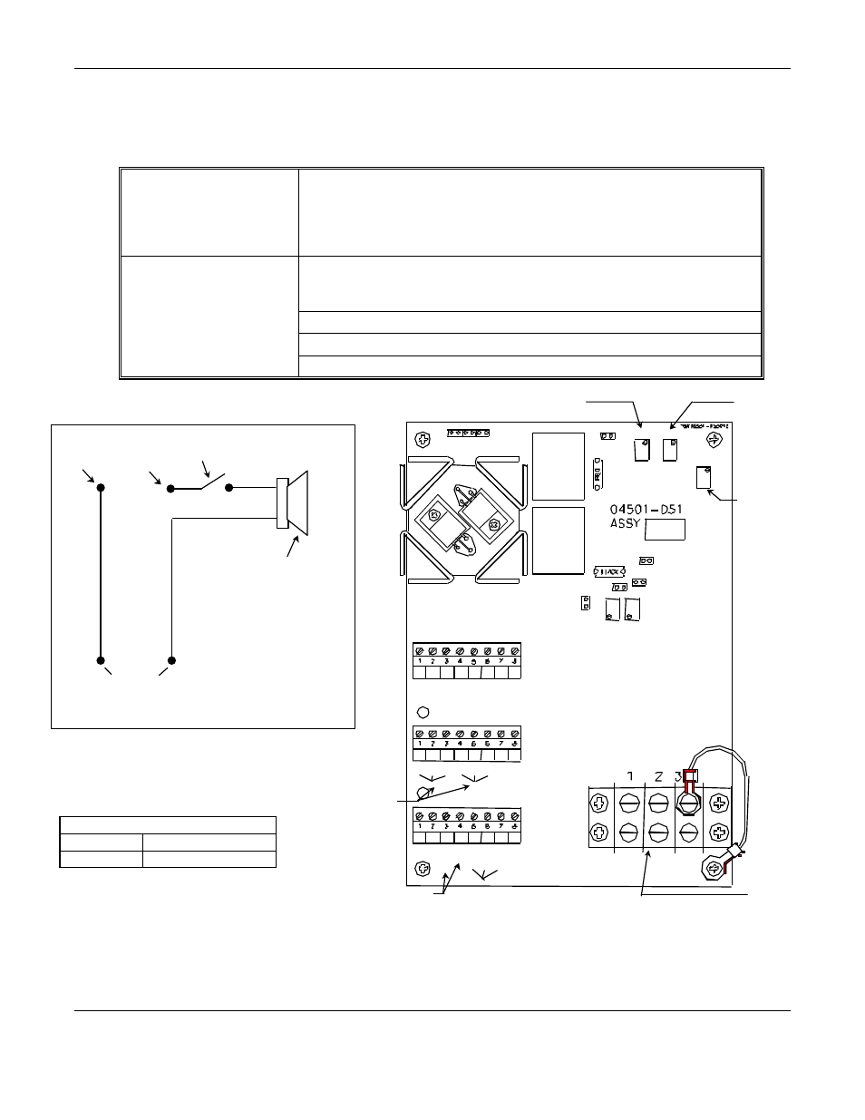
3.2 Internal Electronic Circuitry
Figure 5 shows the circuit board and terminal blocks housed inside the hinged oiltight control unit. Specific relays and
adjustments are defined:
Internal Relay Contacts
Relays can be used to activate an external remote alarm signal when a
hazardous CO level is detected, or when the ac or dc power is interrupted.
These are double-pole relays with terminals normally open, normally closed
and common (see Figure 3 for relay contact hook-up). There is one relay for
each alarm level.
Potentiometers:
The unit has five potentiometers. Only 3 are used by the customer. These vary
critical circuit resistances and are essential to calibration procedures. These
potentiometers are described below.
Meter Adjust
To adjust and set the meter for appropriate gas response during calibration.
Low Level Set
To adjust the trip level of the amber gas alarm light and the audio alarm.
High Level Set
To adjust the trip level of the red gas alarm light and the audio alarm.
Figure 3: Utilizing the Relay Contacts
Figure 5: Internal Electronic Circuitry
Normally
Closed
Contact
Common
Contact
110 Vac
Power supply Outside
of Control Unit
Manual On/Off
Switch
Horn
White
Black
Non-Latching Relay contacts:
Identified below is the non-powered
(power to unit is off), alarm positions of
the non-latching relay contacts.
Terminal Block 2 see Figure 5
Relay 1
High Alarm
Relay 2
Low Alarm
N
OTE
:
N.C.= normally closed
N.O.= normally open
Suggested wiring configuration for Utilizing Relay Contacts
(manual on/off switch is suggested; user supplied component)
Low Level Set
Potentiometer
High Level Set
Potentiometer
Meter Adjust
Potentiometer
110 / 115
OR
210 / 230*
*See Section 4.0
12 VDC
INPUT
Internal Relay
Contacts
Red Lamp
----
Green Lamp
Amber Lamp
Purge
GND
Meter+
Meter–
TB3
TB2
TB1
Relay 1
GND
GND
Battery
Backup
GND
GND
Signal
Heater
Sensor
COM
.
N.C.
COM.
N.O.
N.O.
N.C.
Relay 2
TB4
GND
110 VAC
110 VAC
RV34
RV32
RV38
RV35
TP1
RV33
K1
K2
Jumper Holder
Jumper 1
Jumper 2
Jumper 5
Jumper 4
Jumper 3
TP2