Assemble components to the pc board, Figure a, Figure b – Elenco 015V Power Supply Kit User Manual
Page 6: Figure c, Warning, Figure d
-5-
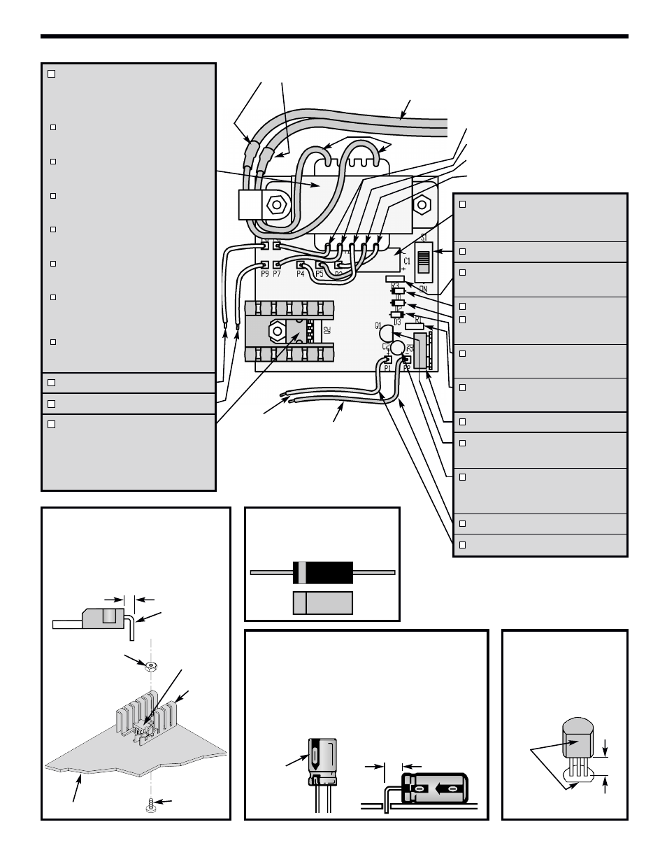
ASSEMBLE COMPONENTS TO THE PC BOARD
Figure A
Bend the leads of the transistor in the direction
shown below.
Install the transistor with the heat sink onto the
component side of the PC board using the
screw and nut as shown. Solder the leads of
the transistor and cut off the excess leads.
Figure B
Diodes have polarity. Mount them
with the band in the correct direction,
as shown on the PC board.
Figure C
Electrolytic capacitors have polarity. Be sure to mount them
with the negative (–) lead (marked on side) in the correct
hole. Bend the capacitor as shown.
Warning:
If the capacitor is connected with incorrect polarity, it
may heat up and either leak, or cause the capacitor to
explode.
Polarity
Marking
Figure D
Mount the transistor with the
flat side in the same direction
as shown on the PC board.
Solder and cut off the excess
leads.
* Strip 1/4” of insulation off of both ends of the wire.
C1 - 1000µF Electrolytic Cap.
(see Figure C)
(Mount Horizontally)
S1 - Slide Switch
R3 - 2.7kΩ 5% 1/4W Resistor
(red-violet-red-gold)
D1 - 1N4001 Diode
D2 - 1N4001 Diode
(see Figure B)
D3 - 1N5247 Zener Diode
(see Figure B)
R1 - 1kΩ 5% 1/4W Resistor
(brown-black-red-gold)
R2 - 10kΩ Potentiometer
Q1 - 2N3904 Transistor
(see Figure D)
C2 - 100µF Electrolytic Cap.
(see Figure C)
(Mount Vertically)
P2 - 3” Blue Wire *
P1 - 3” Red Wire *
Flat
T1 - Transformer, two 6-32 x
5/16” Screws, two 6-32 Nuts,
Shrink Tubing, Cable Clamp, &
Line Cord
Cut the shrink tubing into two 1” sections.
Slip a section of tubing onto each of the
two lead wires on the line cord.
Twist each of the two wires on the line
cord with the two black wires from the
transformer. Solder these wires.
Slide the shrink tubing down over both
black wires to cover the solder joints.
Doing this will prevent a shock hazard.
Keeping your soldering iron close, but
not touching, let the heat from the iron
shrink the tubing.
Using two screws, two nuts and a cable
clamp, install the transformer onto the
PC board.
Cut a 3” section off of each of the red,
yellow, and blue transformer leads.
They will be used later. Strip 1/4” off of
the leads.
Solder the two yellow, two red and one
blue lead from the transformer to the
pads of the PC board as shown.
P8 - 3” yellow wire *
P9 - 3” yellow wire *
Q2 - 2N6121/HT1061 Transistor
Heat Sink
6-32 x 5/16” Screw
6-32 Nut
(see Figure A)
E B C
1/4”
1” Shrink Tubing
Blue Wire
Line Cord
Red Wire
Black
Transformer
Wires
Yellow Transformer Wire
Blue Transformer Wire
Yellow Transformer Wire
Red Transformer Wires
6-32 X 5/16”
Screw
6-32 Nut
Heat sink
PC Board
2N6121/HT1061
Transistor
Bend leads 90
O
1/8”
1/8”