Installation procedure – DuraVent DuraConnect User Manual
Page 6
6
of a firestop plate at the ceiling.
For multiple gas installations, such as
a furnace and hot water heater, a wide
selection of "Tees" and "Y's" are available
in single wall or double wall (B-vent).
Note: Providing the "TEE" or "Y"
connectors are attached to the Type B
gas vent in it's fully twist-lock position,
no screws are required for fastening.
However, if the branch on the "TEE" or
"Y" is angled in some desired direction,
and as a result the fitting is not in it's
fully twist-locked position, the fitting
should be fastened with one or more
sheet metal screws.
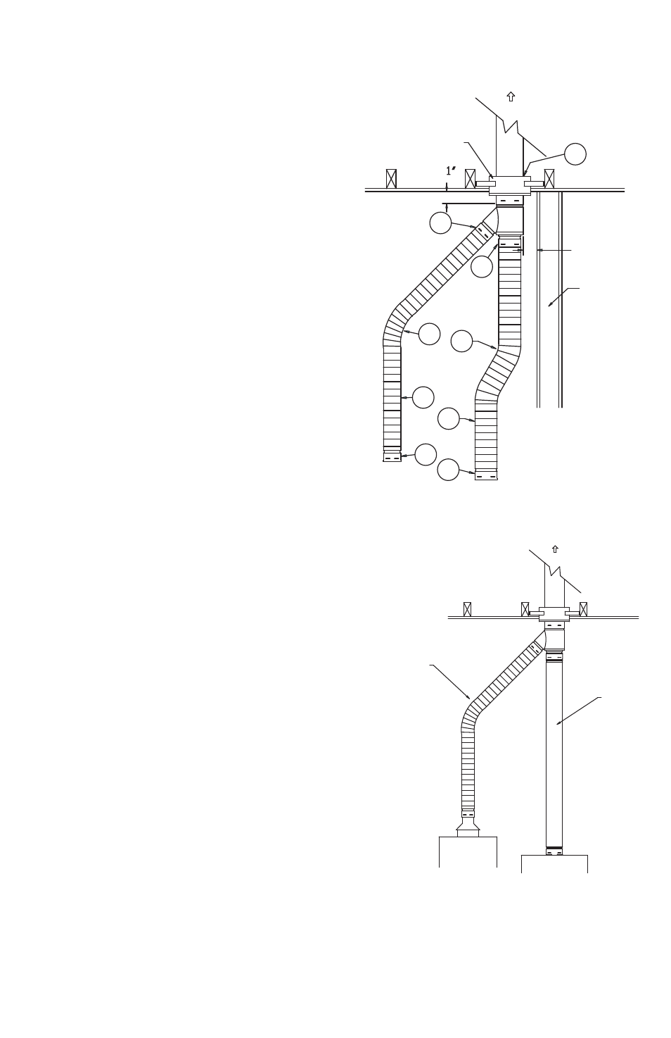
INSTALLATION PROCEDURE
Step 1. Secure Type B gas vent such that
it protrudes a minimum of 1 inch into
the room from a combustible ceiling or
wall. Use a DuraConnect round ceiling
support or wall straps.
Step 2. For a single appliance, simply
twist-lock the flex pipe directly into the
Type B gas vent. As an alternative, the
flex pipe may be attached to the branch
of a "Tee", with the tee cap installed in
the base of the tee.
Step 3. For common venting multiple
appliances, twist-lock a double wall or
single wall "TEE" or "Y" to the Type B gas
vent, then simply twist-lock the flexible
connectors into the TEE or Y fitting.
Step 4. Bend the flexible connector
into position. Avoid dips or sags, and
maintain a minimum 1/4 inch per foot
rise. When possible, use gradual "sweep"
type bends for optimum draft and flow
performance.
Step 5. Attach the flexible pipe to the
outlet of the applianceby using a Draft
Hood Connector for DuraConnect II
1"
WALL
FURNACE
B-VENT
WATER HEATER
CEILING
SDV SUPPORT
1
2
2
3
3
4
4
5
5
FURNACE ROOM,
GARAGE
1"
Figure 1
Figure 2
WATER HEATER
B-VENT
FURNACE
FLEX CONNECTOR
B-VENT