Dunkirk Q90-200 Series II User Manual
Page 6
6
Locating The Boiler
1.
Select level location, central to piping systems served
and close to vent and air intake terminals as possible.
2.
Manufacture recommended accessibility clearances, if
more stringent (i.e. larger clearances) than required
fire protection clearances, must be used for boiler
installation. Accessibility clearances may be achieved
with use of removable walls or partitions.
3.
Combustible clearances shown in Table 4 indicate
required clearances per CSA listing. Minimum 1”
(25 mm) clearance must be maintained between
combustible construction and each of the right, top
and back surfaces of boiler. Minimum 8” (203 mm)
clearance is required on left side, to allow room for inlet
air pipe. 18” (457 mm) clearance must be maintained
at front where passage is required for cleaning or
servicing, inspection or replacement of any parts
that normally require such attention. Allow 24” (610
mm) at front and left side and 8” (203 mm) at top for
servicing. No combustible clearances are required to
venting or combustion air intake piping.
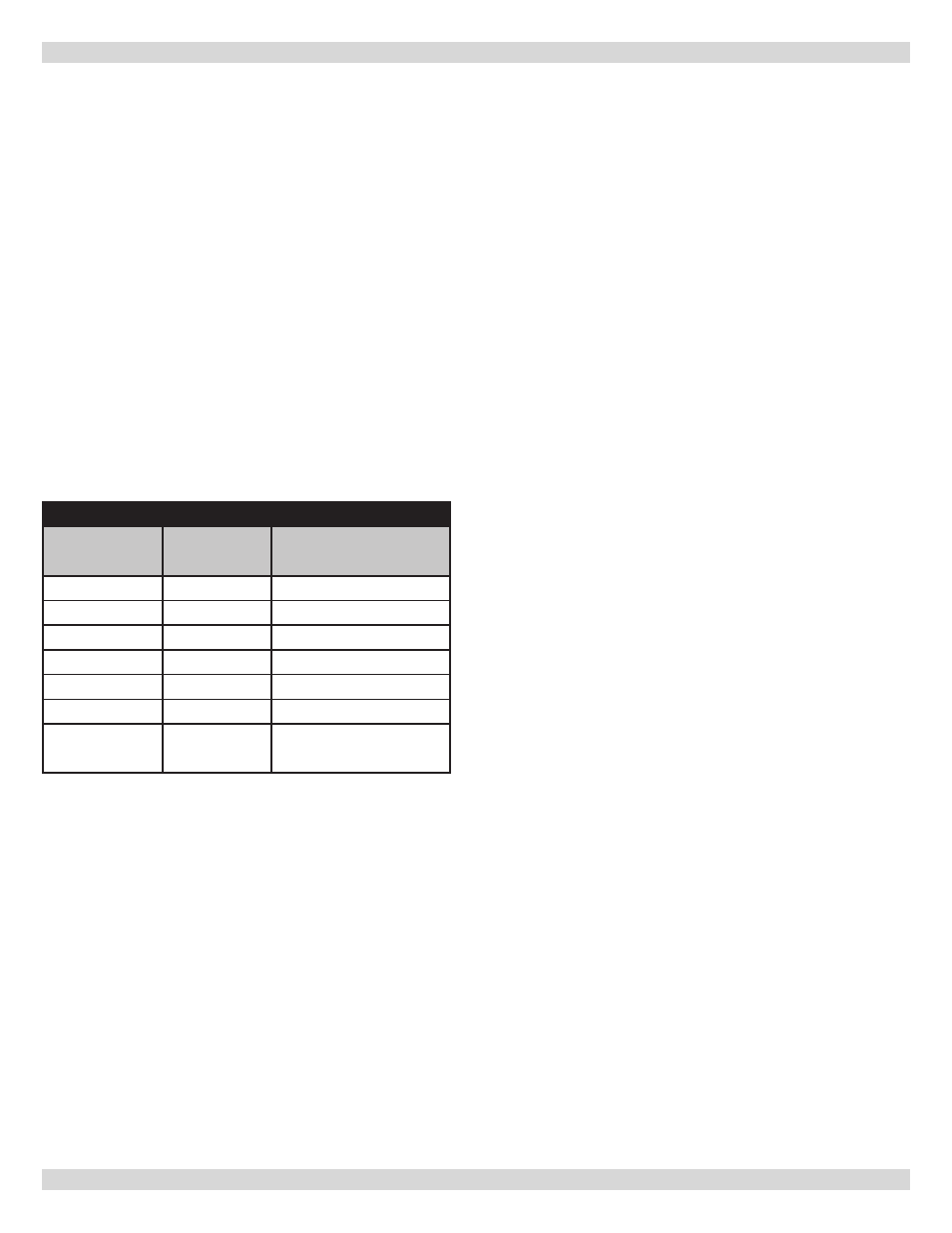
Table 4 - BOILER CLEARANCES
Unit
Combustible
Clearance
Accessibility, Cleaning,
and Servicing
Top
1” (25 mm)
8” (203 mm)
Left Side
8” (203 mm)
24” (610 mm)
Right Side
1” (25 mm)
-
Base
1” (25 mm)
-
Front
0” (0 mm)
24” (610 mm)
Back
1” (25 mm)
-
Intake/Vent
Piping
0” (0 mm)
-
All distances measured from boiler cabinet.
4.
Keep boiler area clean of debris and free of flammable
and combustible materials, liquids and vapors.
5.
Install equipment in location which facilitates operation
of venting and combustion air intake piping systems as
described in this manual.
6.
Advise owner to keep venting and combustion air
intake passages free of obstructions. Both venting
and combustion air intake piping systems connected
to outdoors must permit flow through piping systems
without restrictions for boiler to operate.
7.
Boiler shall be installed such that automatic gas
ignition system components are protected from water
(dripping, spraying, rain, etc.) during operation and
service (circulator replacement, condensate trap,
control replacement, etc.).
8.
Boiler must be located where ambient temperatures
(minimum possible room temperatures where boiler
is installed assuming boiler is not in operation and
therefore contributes no heat to space) are always
above freezing temperature.
9.
If boiler is not level condensate drain lines will not
function properly. Adjustable feet are located on boiler
to make up for minor surface irregularities or tilt.
10.
Wood frame or blocks may be used to raise boiler
to maintain drain pitch or to be above external
condensate pump reservoir.
11.
Provide means for condensate drainage.
3 - LOCATING THE BOILER
Removal Of Existing Boiler From Common Vent
System
When an existing boiler is removed from a common
venting system, the common venting system is likely to be
too large for proper venting of the appliances remaining
connected to it. At the time of removal of an existing boiler,
the following steps shall be followed with each appliance
remaining connected to the common venting system
placed in operation, while the other appliances remaining
connected to the common venting system are not in
operation.
1.
Seal any unused openings in the common venting
system.
2.
Visually inspect the venting system for proper size and
horizontal pitch and determine there is no blockage
or restriction, leakage, corrosion or other deficiencies
which could cause an unsafe condition.
3.
In so far as is practical, close all building doors and
windows and all doors between the space in which the
appliances remaining connected to the common venting
system are located and other spaces of the building.
Turn on clothes dryer and any appliance not connected
to the common venting system. Turn on any exhaust
fans, such as range hoods and bathroom exhaust, so
they will operate at maximum speed. Do not operate a
summer exhaust fan. Close fire dampers.
4.
Place in operation appliance being inspected. Follow
lighting instructions. Adjust thermostat so appliances
operate continuously.
5.
Test for spillage at draft hood relief opening after 5
minutes of main burner operation. Use flame of match
or candle, or smoke from cigarette, cigar or pipe.