Multi-mask imager installation – Da-Lite Multi Mask Imager User Manual
Page 4
4
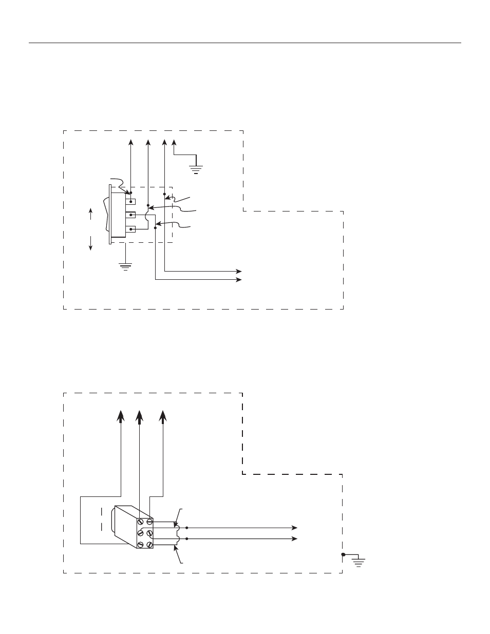
Installing the High Voltage Switch Control (Standard)
Three standard 3-position wall switches are supplied. The high-voltage control is connected to the electrical source.
It alternates directions of mask motion by means of a hot lead, using the 3-position switches.
Multi-Mask Imager Installation
Do
wn R
ed
Up Black
Common
Whit
e
Black With
Yellow
Black
White
Red
Up
Down
Rocker
Switch
AC Common
AC Hot
Operating Switch,
Switch Box, And
Plate Furnished
With Screen
(SPDT With
Center Off)
120V. 60-HZ 2.5 Max. Amp
To Motor
In Multiple Control
Installations This Switch
Is Replaced By The Low
Voltage Control,
Operated From Push
Button Stations.
This Switch Cannot Be Used With LVC.
NOTE: A single switch cannot be used to operate more than
one screen. Contact the factory for further information.
Side View
Of Switch
And Box
120V Wiring Diagram
220 / 240V
Wiring Diagram
Br
o
wn (Up)
Black (Do
wn)
Blue (Common)
Brown/Yellow
Up
Off
Down
Rocker
Switch
Blue AC Common
Brown AC Hot
Operating Switch,
Switch Box, And
Plate Furnished
With Screen.
Blue Jumper Wire
To Motor
NOTE:
Must Be Wired To Conform To
Local Wiring Code. This Switch
Cannot Be Used With L.V.C.
220/240V. AC 50HZ
2 Amp. Max
Junction
Box
In Multiple Control
Installations This Switch Is
Replaced By The Low
Voltage Control, Operated
From Push Button Stations.
NOTE: A single switch cannot be used to operate more than
one screen. Contact the factory for further information.
Rear View Of DPDT,
With Center Off
Off