Babbitt LS7000/2 Dual-Point Sensor User Manual
Page 8
4. CALIBRATION
PLEASE READ THE ENTIRE CALIBRATION PROCEDURE BEFORE CALIBRATING THE LS7000/2.
A. Setting S1 and S2
Switches S1 and S2 are the dip switches on the LS7000/2 sensing card. S2 selects automatic fill or automatic
empty.
“AUTOMATIC FILL” is when the relay energizes below the low setpoint and de-energizes below the high
setpoint.
“AUTOMATIC EMPTY” is when the relay energizes at the high setpoint and de-energizes below the low
setpoint.
The green LED indicates relay status. The green LED is on when the relay is energized.
When S2 is UP, “AUTOMATIC FILL” is selected.
When S2 is DOWN “AUTOMATIC EMPTY” is selected.
S1 is used to select the “POWER-ON-RESET” mode of the LS7000/2, if the supply voltage should be
interrupted while the fluid level is between the low and high setpoints. If the unit should lose power and the
level is between the
setpoints, the LS7000/2 can not “remember” if it was filling or emptying at the time of
power loss. By properly setting S1 for your application, the relay will either energize or de-energize when
power is restored to the unit. If the fluid level is below the low setpoint or above the high setpoint, S1 has no
effect on the operation of the unit.
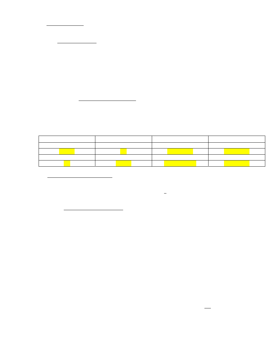
The chart below will help you set S1 and S2:
S1
S2
FILL/EMPTY
Power On Reset
UP
UP
AUTO FILL
RELAY OFF
DOWN
UP
AUTO FILL
RELAY ON
DOWN
DOWN
AUTO EMPTY
RELAY OFF
UP
DOWN
AUTO EMPTY
RELAY ON
B. Setting the Sensitivity Switch
The LS7000/2 plug in board has a 2 position slide switch to set the sensitivity.
As a rule of thumb, use low sensitivity for conductive liquids or long probes. High sensitivity is for non-
conductive liquids or short probes. (See diagram on page 4 for switch location)
C. Calibrate the Low Setpoint
There are two ways to calibrate the low setpoint. Method “A” puts the setpoint on the bottom tip of
the probe. Method “B” is for applications where the low setpoint needs to be above the tip of the
probe.
METHOD “A”
1. When no product is in contact with the probe, observe the red LED for the low setpoint. If it is on,
go to step 3.
2. If the red LED for the low setpoint is off, turn the low adjustment potentiometer CW until it comes
on.
3. Turn the low adjustment potentiometer CCW until the low red LED just goes out.
METHOD “B”
1. Raise the fluid level to where you want the low setpoint to be on the probe.
2.
Observe the red LED for the low setpoint. If it is off, go to step 4.
3. If the red LED is on, turn the low adjustment potentiometer CCW until the red LED goes out.
4. Turn the low adjustment potentiometer CW until the low red LED just comes on.
6