Jumper and connector list – Avalue EEV-Q702 User Manual
Page 8
EEV-Q702
8 EEV-Q702 Quick Installation Guide
2.2 Jumper and Connector List
You can configure your board to match the needs of your application by setting jumpers. A
jumper is the simplest kind of electric switch.
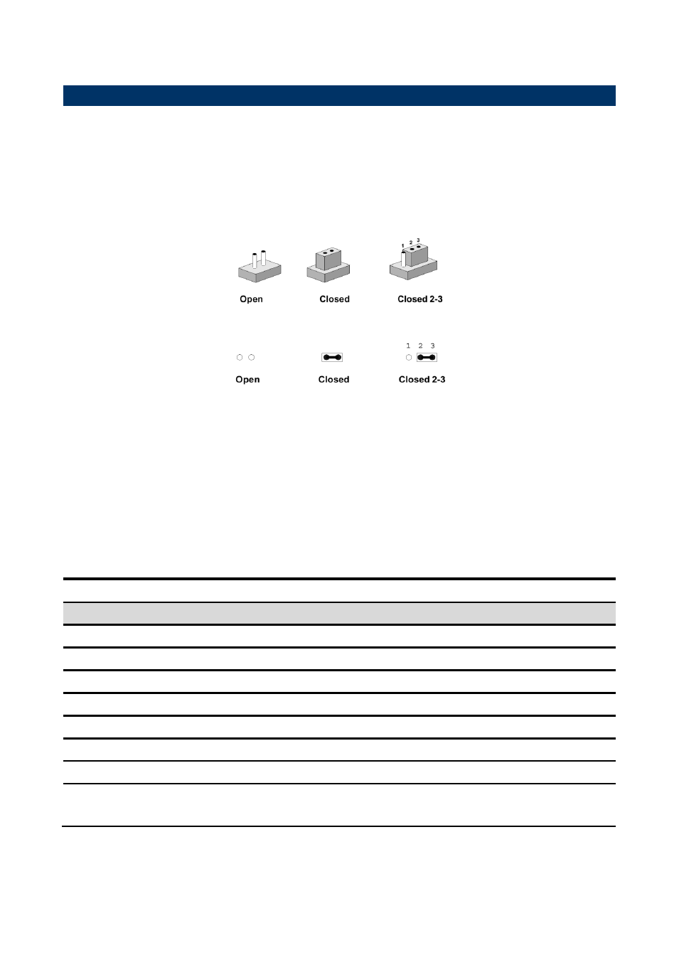
It consists of two metal pins and a small metal clip (often protected by a plastic cover) that
slides over the pins to connect them. To “close” a jumper you connect the pins with the clip.
To “open” a jumper you remove the clip. Sometimes a jumper will have three pins, labeled 1,
2, and 3. In this case, you would connect either two pins.
The jumper settings are schematically depicted in this manual as follows:
A pair of needle-nose pliers may be helpful when working with jumpers.
Connectors on the board are linked to external devices such as hard disk drives, a
keyboard, or floppy drives. In addition, the board has a number of jumpers that allow you to
configure your system to suit your application.
If you have any doubts about the best hardware configuration for your application, contact
your local distributor or sales representative before you make any changes.
The following tables list the function of each of the board's jumpers and connectors.
Jumpers
Label
Function
Note
JPCIESEL
PCIE signal selector
3 x 1 header, pitch 2.00mm
JUSB_PW
USB power selector
3 x 1 header, pitch 2.00mm
JAT_ATX
AT/ ATX Input power select
3 x 1 header, pitch 2.00mm
JCMOS
Clear CMOS
3 x 1 header, pitch 2.00mm
JBIOS
Module/Carrier BIOS selector
3 x 1 header, pitch 2.00mm
JUSBSEL
USB Port selector
3 x 1 header, pitch 2.00mm
JEDPLVDS eDP/ LVDS selector
3 x 1 header, pitch 2.00mm
JQ7_VER
JDPQVER selector
DP for Q7 1.2 VS 2.0
3 x 1 header, pitch 2.00mm