2 > qd alarm connection & operation – Austin Hughes RP-919QD User Manual
Page 13
UM-CV-751-RP-919QD-Q215V1 www.austin-hughes.com
< 4.2 > QD ALARM Connection & Operation
RP-919QD
3 Sensor Activated Alarm
The unit is equipped with 4 alarm sensor inputs. If any alarm is activated:
■
the built-in buzzer and the alarm output control relay contact will be activated.
■
the quad will switch the corresponding channel indicator LED to blinking mode.
■
a warning message depending on different models will be displayed as follows:
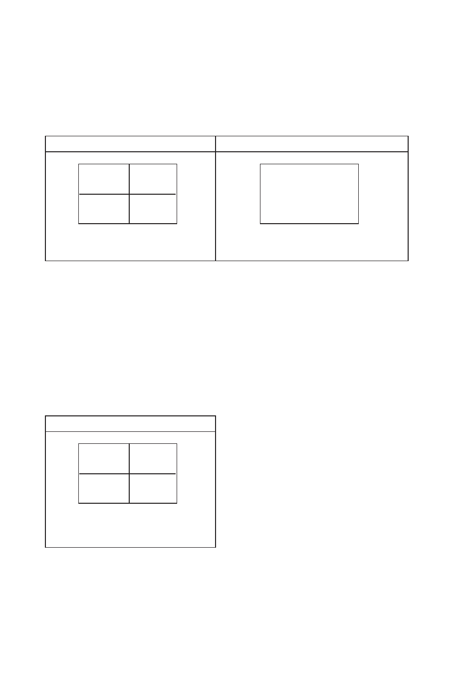
Quad output channel (#4)
LIVE output channel (#5)
Blinking Alarm & Title message on the
activated channel in quad screen
Full screen display of the activated channel.
Also display a blinking Alarm message
Alarm
Alarm
Above mentioned alarm can be cleared by any of the following: 1. Connecting the Alarm Reset In contact, pin #5, of the
female type 9 pin D-sub connector (#8) to GND. 2. The Alarm Duration time elapses. 3. If the device is operated under
Security Lock ON mode, Push Lock button for 2 seconds to disable the function then push any button in the front panel.
4 Video Loss Alarm
Loss of video at any input is automatically detected by the device. The device will:
■
Activate the built-in buzzer.
■
Switch the corresponding channel indicator LED to blinking mode.
■
Display warning message on quad screen:
Quad output channel (#4)
Blinking Video Loss & Title message
on the activated channel in quad
screen
Video loss
■
The warning message and the buzzer can be cleared
by pushing Lock button (#2) for more than 4 seconds if the
device is operated under Security lock On mode, or pushing
any button on the front panel if the device is operated under
Security lock OFF mode.
P.10