Daewoo DVT-14/20H1(T)F User Manual
Page 7
6
ALIGNMENT INSTRUCTIONS
5.5 HORIZONTAL CENTER
1) Apply a RETMA PATTERN SIGNAL.
2) Adjust picture centering with H-CENTER +/- KEY.
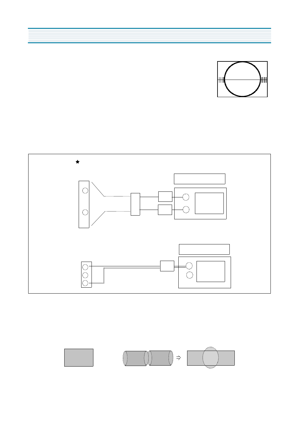
6. DECK ADJUSTMENT
6-1. X-POSITION AND P2,P3 ADJUSTMENT
1) Adjust point : X-POSITION
Checking point : oscilloscope ch1 = H/SW (PY03 #2)
oscilloscope ch2 = PB ENVE (PY03 #4)
Triggering : CH1
Measuring Equipment : oscilloscope, path jig
Mode : PLAYBACK,ATK OFF
Test tape : DP-2 (6KHz)
* Adjustment Procedure
1) Connect the PATH JIG to PY03 after Test tape PLAYBACK
2) Insert the DP-2 TAPE. ( Auto playback)
3) Pressing the "ATK OFF" KEY.
4) Adjust the waveform of PB ENVE to maximum(figure1) using X-position VR.
5) Adjust IN/OUTPUT GUIDE until the exact waveform appear as bellow figure2.
OSCILLOSCOPE1
OSCILLOSCOPE2
CH2
CH1
ADJUST JIG
CONNECTION METHODE
PY03
P601
1
2
2
4
3
CH1
max.
(figure 1)
(figure 2)