English, Bevel detent (dc300 only), Shoe adjustment for 90˚ cuts – DeWalt DW9116 User Manual
Page 15: Kerf indicator
English
14
making any adjustments or removing/installing attachments
or accessories.
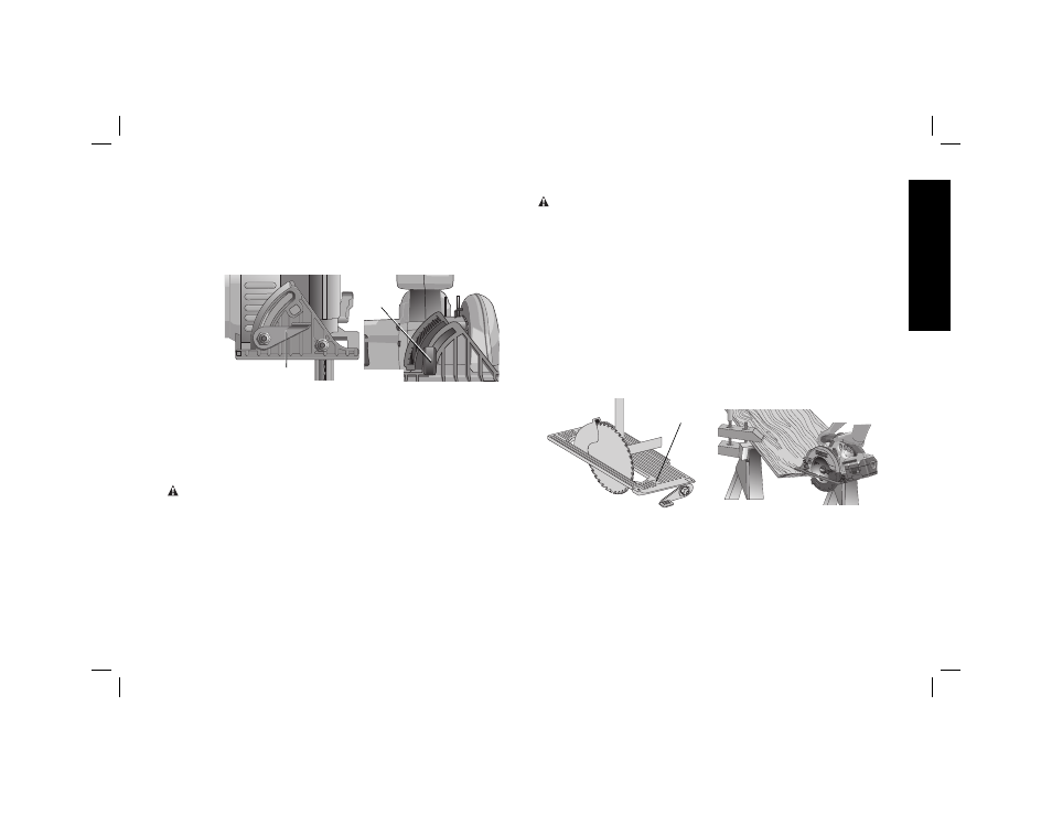
The full range of the bevel adjustment is from 0˚ to 50˚.
The pivot bracket is graduated in increments of 1˚. On the
front of the saw is a bevel angle adjustment mechanism
(Fig. 11) consisting of a calibrated pivot bracket and a bevel
adjustment lever (DC300) or knob (DC310).
J
DC300
J
DC310
FIG. 11
TO SET THE SAW FOR A BEVEL CUT (FIG.11)
1. Raise the lever or knob (J) to loosen the bevel adjustment and
tilt shoe to the desired angle by aligning the pointer with the
desired angle mark.
2. Retighten the bevel adjustment by lowering the lever.
Bevel Detent (DC300 only)
WARNING: To reduce the risk of serious personal injury,
turn tool off and disconnect tool from battery pack before
making any adjustments or removing/installing attachments
or accessories.
The saw is equipped with a bevel detent feature. As you tilt the
shoe you will hear a click and feel the shoe stop at both 22.5 and
45 degrees. If either of these is the desired angle, retighten the
lever (J) by lowering it. If you desire another angle, continue tilting
the shoe until the pointer aligns with the desired mark. Retighten
lever (J) by lowering it.
Shoe Adjustment for 90˚ Cuts
WARNING: To reduce the risk of serious personal injury,
turn tool off and disconnect tool from battery pack before
making any adjustments or removing/installing attachments
or accessories.
IF ADDITIONAL ADJUSTMENT IS NEEDED (FIG. 12)
1. Adjust the saw to 0˚ bevel.
2. Retract blade guard. Place the saw on blade side.
3. Loosen bevel adjustment lever or knob (J). Place a square
against the blade and shoe to adjust the 90˚ setting.
4. Turn the adjustment screw (K) on the underside of the shoe
until the blade and the shoe are both in flush contact with the
square. Retighten the bevel adjust lever or knob.
5. Confirm the accuracy of the setting by checking the squareness
of an actual cut on a scrap piece of material.
FIG. 12
K
FIG. 13
Kerf Indicator
The front of the saw shoe has a kerf indicator for vertical and bevel
cutting. This indicator enables you to guide the saw along cutting
lines penciled on the material being cut. The indicator lines up
with the left (outer) side of the saw blade, which makes the slot or
“kerf” cut by the moving blade fall to the right of the indicator. Guide
along the penciled cutting line so that the kerf falls into the waste
or surplus material.