Features, Installation, Adaptor requirements – Aiphone PG-60A User Manual
Page 2: Amplieier input connections
Attention! The text in this document has been recognized automatically. To view the original document, you can use the "Original mode".
FEATURES
Designed for use with AIPHONE intercoms in conjunction with paging adaptor.
Full range volume and tone controls on paging adaptor.
Amplifier output may be either 25V or 70.7V constant voltage balanced loads.
Complimentary transistor at the output stage ensures extreamly low distortion and high damping factor.
* Circuit breaker protects internal circuit against overloaded or shorted output line.
* May be shelf or wall mounted.
INSTALLATION
Do not attempt to install your PG-A amplifier until you have read and thoroughly understood the installation
procedure. Aiphone’s warranty for the amplifier and the system is void if amplifier is installed in a manner other than
described in this manual.
ADAPTOR REQUIREMENTS
The following AIPHONE intercoms have paging capability and may be connected to PG-A amplifier in conjunction
with a paging adaptor. The type of adaptor must be decided according to the type of intercom system you install and the
paging mode you wish to have. Each paging block requires one PG-A amplifier and appropriate number of speakers.
TYPE OF
INTERCOM
ADAPTOR REQUIREMENTS
STRAIGHT PAGING
BLOCK PAGING
TALKBACK PAGING
® TA-F
one PG-U
not available
one PG-U and one PA-B
®
TA-H
(3) TA-Y
one PG-U
one PG-U and one PA-B per block
one PG-U and one PA-B per block
0 TS-K
one PG-U
one PG-U and one PA-B per block
one PG-U and one PA-B per block
@
KAH
one PA-1
one PA-1 per block
one PA-2 per block
© TB-F
one PB-1
not available
one PB-1 and one PB-2
© TB-H
one PB-1
one PB-1 per block
one PB-1 and one PB-2 per block
® MC-3
one MC-A
not available
not available
Begin your installation by connecting the paging adaptor to your intercom system (and background music source
if required) by referring to the instruction sheet of the paging adaptor packed with each unit. Requirements stated on
the instruction sheet of the paging adaptor MUST BE MET.
After completing installation of both intercom system and the paging adaptor, then you may proceed to installation
of PG-A amplifier. Unplug both power supply for intercom system and amplifier while making wiring connections.
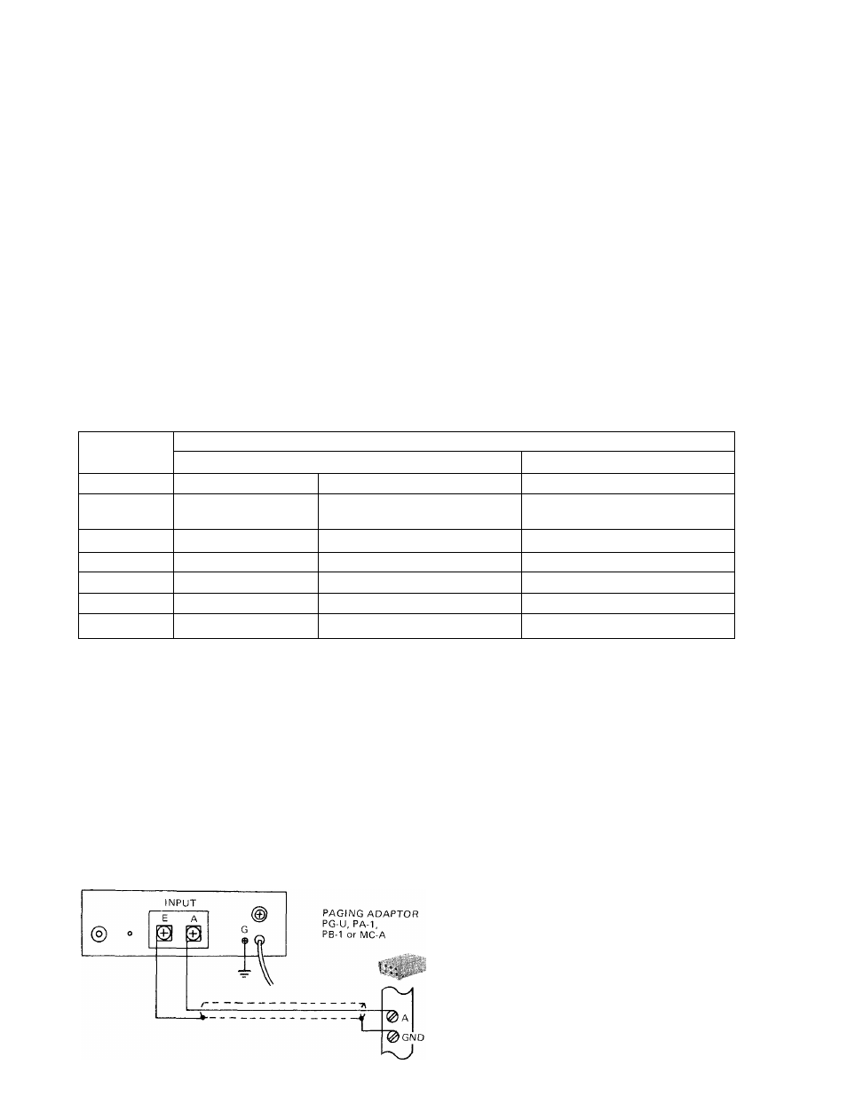
AMPLIEIER INPUT CONNECTIONS
The greater the distance between the paging adaptor and the amplifier will increase the possibility of picking up
R.F. signals or electrical noise.
The paging adaptor and amplifier should be located as close as possible to each other and shielded cable should
always be used to connect them.
PAGING AMPLIFIER
PG-10A, PG-30A or PG-60A
1) Connect output A terminal on paging
adaptor to input A terminal on PG-A
amplifier.
2) Connect output GND terminal on paging
adaptor to input E terminal on PG-A
amplifier.
* G terminal which has a green colored screw
head must be ground for avoiding electric
shock or hazard.