P©p ©p ©p ©p – Adcom GFP-750 User Manual
Page 3
Attention! The text in this document has been recognized automatically. To view the original document, you can use the "Original mode".
1. PRODUCT DESCRIPTION
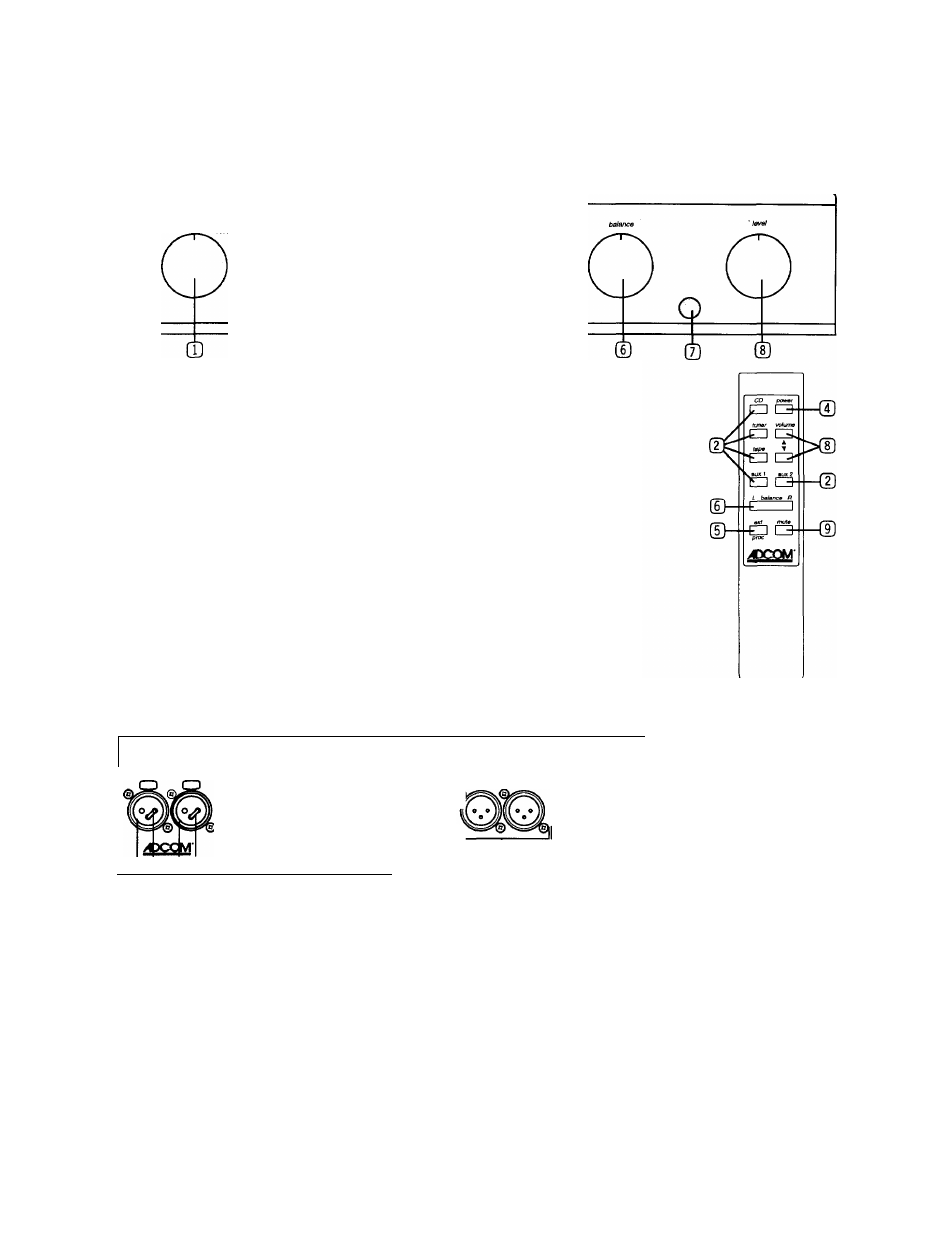
1.1. GFP-750 Front Panel Diagram & Remote Control
0 CD О
О
pa$siv0 power
processor
9
9
9
(Ю ® СЮ
Ш
Stereo/Reverse/Mono
Switch (reverse) or combine (mono) channels
©
Input Source Selection
Select input source
©
Passive Mode On/Off
Bypass active gain stages
Power On/Off
Turn unit on and off.
©
External Processor
Engage external processor
©
Balance Control
Adjust balance level
©
Infrared Remote
Receiver for remote control IR signal
Control Sensor Lens
©
Volume Control
Adjust volume level
©
Mute
Engage Mute circuitry
1.2. GFP-750 Rear Panel Diagram
Γ
top Is L channel bottom is R channel
balanced CO input unbalanced inputs » laps
p processor ^ p unbal outpu& ^ p balancect mam 3 output
@p©p ©p ©p ©p
1
,,@°® @©.@ъ.@©,@°©,
I
10 Timber Lan»
Mariboro, NJ 07746
Mo0elGFP-7S t siBreo preamplitier Wan ng: To r»6uc» the sk ot elactnc sfioc -, do noi expose this equipm nt to rain or moislure.
Power: ItSVAi SO-бОНг
Aire/ ion: pour evitar bv lìrisque de leu au hoc elactrique, ne pas expo:
Pbwarcansun itìon(max):30W Avis: Vaque líe choc ek Л
1
рае-ne pese
0^ ®
© ©
® CD Balanced Inputs
©
(TI) Gold Jumpers
QD Unbalanced Stereo Inputs
©
(B) Tape Loop Stereo In/Out
©
@ External Processor
Loop Stereo In/Out
©
IR expar/der remote sensor
©
switched АС outet
Л
о о.
©
О.
©
' се! аррвгеН а Ш phiie с
"АН
Main 1 and Main 2
Unbalanced Stereo Outputs
Main 3
Balanced Stereo Outputs
Remote Control Infrared
repeater outputs (x 2)
Remote Control
Sensor Input
Master On/Off Switch
AC Power Cord Socket
Switched AC Outlet