Connecting card reader – Atech Flash Technology XM-35U User Manual
Page 6
Attention! The text in this document has been recognized automatically. To view the original document, you can use the "Original mode".
Connecting Card Reader
1. open computer case cover. Please refer to your computer manual if necessary.
2. Insert XM-35U into empty 3.5" drive bay.
3. Apply screws on each side of unit to secure to chassis,
4. Connect Internal USB cables to unit then to Motherboard USB header pin
5. For external use, connect the External USB cable to back of unit.
/ Left USB is for Reader
Right USB is for front USB port
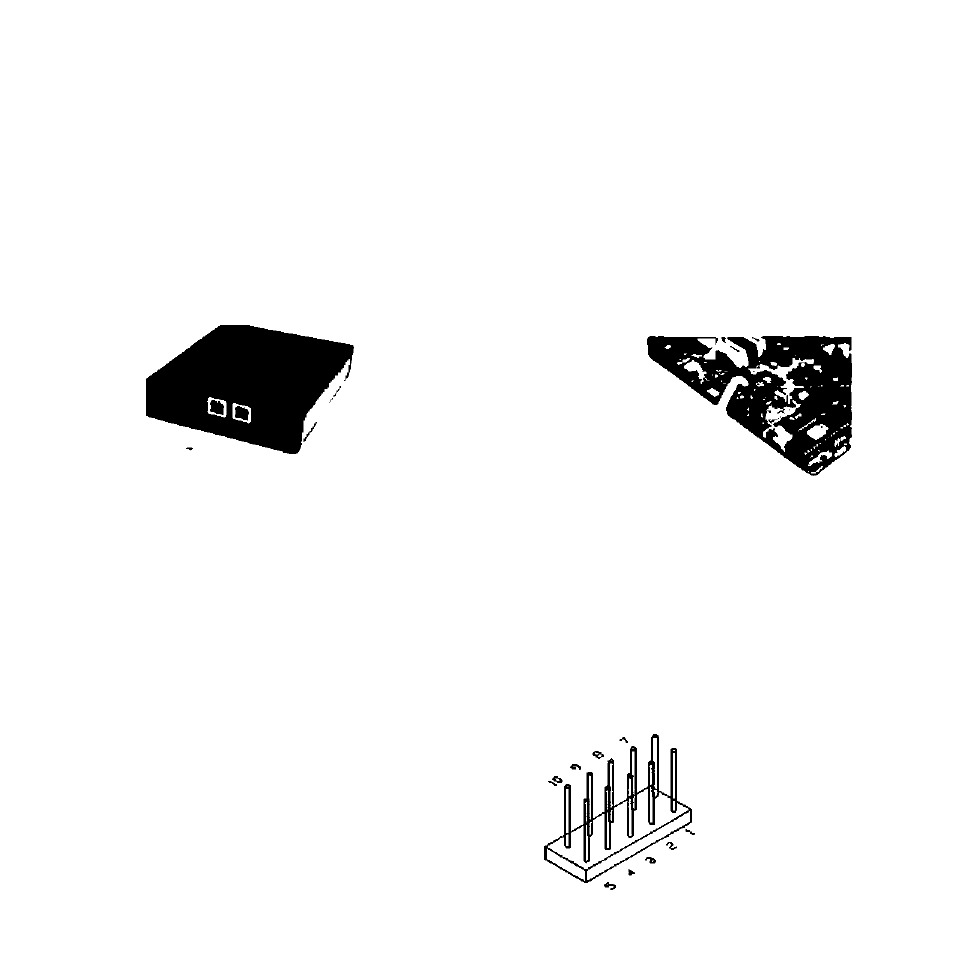
Mothertxtard connection
Depending on the pin layout on your motherboard USB header, it may be necessary to
rearrange the color wires of Internal USB cable to match the USB pin assignment.
Please refer to your motherboard manual for USB header pin assignment information.
Internal USB cable consists of Red. White. Green and Black wires. Each color wire shall
be connected to a specific pin on the USB header.
Red wire = Power (VCC)
White wire = P- (Data-)
Green wire = P+ (Data+)
Black wire = Ground (GND)
Pm 1 s u&B Power
Pm 2 » US6P2-
Pm 3 • US8P2*
Pm4«0ND
Pm5s^н:
Pm 6 • US6 Power
Pln7*US6P3-
Pm 8 s U$BP3*^
Pin 9 s GND
Pm 10 9 NC (No pin)