Suggested specifications – A.O. Smith DB-720 thru 1810 User Manual
Page 3
Attention! The text in this document has been recognized automatically. To view the original document, you can use the "Original mode".
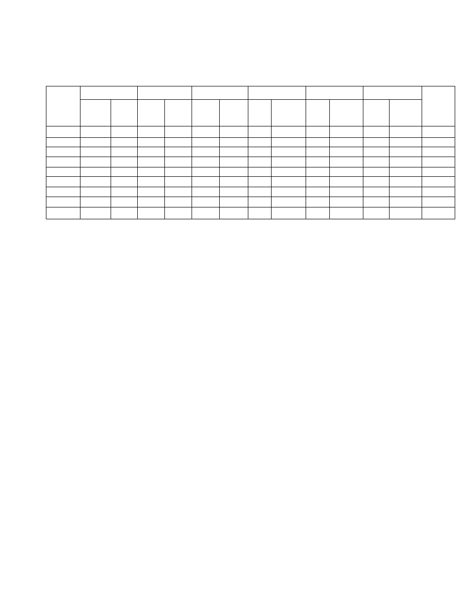
BOILER RATE OF FLOW AND PRESSURE DROP
Model
Number
Temp. Rise 20°F
Temp. Rise 30°F
Temp. Rise 40°F
Temp. Rise 10°C
Temp. Rise 15°C
Temp. Rise 20°C
Model
Number
Head
Flow
(gpm)
Head
Loss
(Feet)
Flow
(gpm)
Head
Loss
(Feet)
Flow
(gpm)
Head
Loss
(Feet)
Flow
(Ips)
Head
Loss
(meters)
Flow
(Ips)
Head
Loss
(meters)
Flow
(Ips)
Head
Loss
(meters)
720
59
3.5
40
1.7
3o
1.0
4.2
1.16
2.8
0.56
2.1
0.36
720
840
69
4.8
46
2.1
35
1.5
4.9
1.89
3.2
0.76
2.4
0.58
840
960
79
6.8
53
3.3
40
1.9
5.6
2.42
3.7
1.15
2.8
0.69
960
1080
89
4.5
59
2.1
45
1.4
6.2
1.62
4.2
0.81
3.1
0.51
1080
1210
100
5.3
67
2.7
50
1.6
7.0
1.96
4.7
0.98
3.5
0.64
1210
1350
111
6.8
74
3.2
56
1.8
7.8
2.35
5.2
1.26
3.9
0.73
1350
1480
122
7.9
81
3.9
61
2.1
8.6
2.91
5.7
1.49
4.3
0.84
1480
1610
133
9.5
89
5.0
66
3.0
9.3
3.55
6.2
1.85
4.7
1.10
1610
1810
149
12.0
100
6.2
75
3.9
10.5
4.19
7.0
2.21
5.2
1.35
1810
NOTE: Pressure drop shown is the loss through the boiler only and does not include any additional piping.
SUGGESTED SPECIFICATIONS
Hydronic boiler shall be A. O. Smith Dura-Max model DB
with an input rating of
BTU/Hr (KW) and having an
output rating of
BTU/Hr (KW). The boiler shall be design certified by the American and Canadian Gas Associations and
shall carry the ASME “H" Symbol. The wet section shall be design registered in accordance with the requirements of the ASME
Code and shall carry an appropriate National Board Number or Canadian Registration Number. All internal waterways shall be
copper, brass or bronze. The heat exchanger shall be a two (2) pass design incorporating integral fin copper tubes. The double
row heat exchanger shall have staggered tubes. Cast bronze return bends shall be readily removable to permit visual inspection
or cleaning without removing the entire wet section assembly. Silicone “O" ring gaskets shall form a water tight seal by compres
sion and shall be isolated from the flue gasses by 3/4" (2cm) board type ceramic fiber insulation. The heat exchanger assembly
shall be hydrostatically tested to a pressure of 240 psi (1655 kPa) and shall have a maximum working pressure of 160 psi (1100
kPa).
The Combustion Chamber shall be constructed of board type ceramic fiber insulation rated to 2300“F (1260“C) which interlock to
form a gas tight seal and shall be supported in a heavy gauge corrugated steel frame. The external cabinet shall incorporate a
built-in draft hood and shall be of baked enamel steel construction. It shall be suitable for installation on combustible flooring. The
burners shall be a stainless steel stamped design and shall be mounted in a removable drawer assembly.
The burner controls shall be 24 VAC and shall include slow opening main gas valve for soft ignition, redundant safety shutoff gas
valve, main and pilot pressure regulators, recycling intermittent pilot system with one second shutdown in the event of pilot flame
failure, automatic recycling high limit, manual reset ECO limit, main and pilot manual cocks, manual firing valve, an ASME rated
pressure relief valve and factory installed flow switch.
The boiler shall comply with the latest edition of ASHRAE/IES 90.lb-1989 (1992 requirements) Standards. Optional: Factory
installed dial-type temperature and pressure gauges shall be mounted on the front of the cabinet.