Chromalox CMB-3A User Manual
Installation, operation, Type cmb electric steam generator, Renewal parts identification
(Supersedes PQ400-8)
PQ400-9
3001H
161-048643-001
JULY, 2009
4
and
Installation, Operation
RENEWAL PARTS IDENTIFICATION
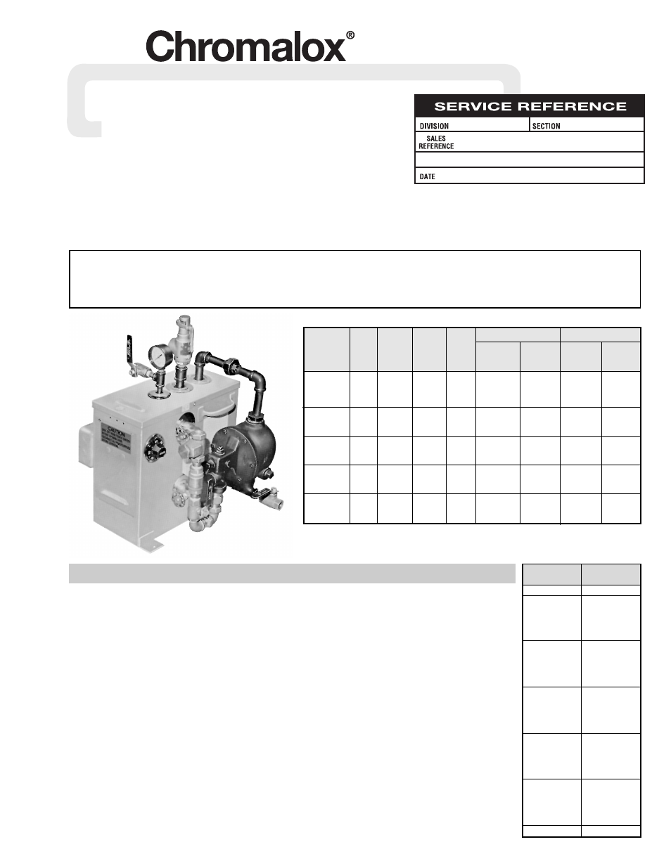
Type CMB Electric Steam Generator
0 – 90 PSI
© 2010 Chromalox, Inc.
Output
Single Phase
Three Phase
Lbs./Hr.
Power
Power
Vol.
AT †
Amperes
CCT.
Amperes
CCT.
Model
kW
(Gals.)
212°F
Volts
Drawn
Diag.
Drawn
Diag.
3
1.6
9
120
25
1
NA
NA
CMB-3A
3
1.6
9
208
14.4
2
8.3
3
3
1.6
9
240
12.5
2
7.2
3
3
1.6
9
480
6.3
2
3.6
3
6
6
18
208
28.8
4
16.7
8
CMB-6A
6
6
18
240
24
4
14.4
8
6
6
18
480
125
4
7.2
8
9
6
27
208
43.3
6
25
8
CMB-9A
9
6
27
240
37.5
5
21.7
8
9
6
27
480
18.8
4
10.8
8
12
6
36
208
57.7
7
33.3
8
CMB-12A
12
6
36
240
50
7
28.9
8
12
6
36
480
25
5
14.4
8
15
6
45
208
72.1
7
41.6
9
CMB-15A
15
6
45
240
62.5
7
36.1
8
15
6
45
480
31.2
5
18
8
Specifications —
GENERAL
WARNING: Hazard of Electric Shock. Any installa-
tion involving electric generators must be effec-
tively grounded in accordance with the National
Electrical Code to eliminate shock hazard.
1. Locate unit on level floor or platform.
2. Connect water line to tagged fitting on the water control feeder.
3. The incoming water supply must be 10 pounds greater than the
operating pressure. Otherwise, a high pressure feed (pump)
must be used.
4. Wire unit following wiring diagrams supplied. (See recom-
mendations on safety switches and fusing.)
5. Connect steam line with an outlet valve to boiler steam outlet.
Chromalox recommends using a globe valve one pipe size
smaller than steam line to limit any pressure drops (surges) that
may occur during start-up.
6. Open all gauge valves and steam outlet valve. Keep drain valve
closed.
7. Turn on watter supply; water will reach operation level auto-
matically.
8. Close steam outlet valves.
9. Set thermostat for desired steam pressure (see Table 1).
10. Turn boiler switch to ON position, pilot light will go on.
Generator will Build up to desired
pressure and shut off automati-
cally.
11. Open steam outlet valves and
use steam as needed.
12. Generator should be blown
down daily (see Blowdown
instructions).
13. Chromalox generators are pretest-
ed before shipment. No internal
wiring or piping is required.
14. Substitution of components or
modification of wiring systems
without consult of manufacturer
voids the warranty.
15. Power must be off when genera-
tor is drained.
16. Purchaser should use a safety
switch between the main power
source and the steam generator.
The safety switch should use cir-
cuit breakers or fuses.
CMB-3A
† Assuming Feedwater at 50°F.
Note — All Models listed with Underwriters Laboratories Inc.
Gauge Pressure
Temperature
(psig)
(°F)
0
212
1
216
2
219
3
222
4
224
5
227
6
230
7
232
8
235
9
237
10
240
15
250
20
259
25
267
30
274
35
281
40
287
45
292
50
298
55
303
60
307
65
312
70
316
75
320
80
324
85
328
90
331
Table 1 —
Temperature-Pressure
Relationship for Steam
Boiler Serial # . . . . . . . . . . . . . . . . . . . . . . . . . . . . . . . . . . . . . . . . . Power Circuit Voltage . . . . . . . . . . . . . . . . . . . . . . . . . . . . . . . . . . . .
Model # . . . . . . . . . . . . . . . . . . . . . . . . . . . . . . . . . . . . . . . . . . . . . . Control Circuit Voltage . . . . . . . . . . . . . . . . . . . . . . . . . . . . . . . . . . .
National Board # . . . . . . . . . . . . . . . . . . . . . . . . . . . . . . . . . . . . . . . Amps. . . . . . . . . . . . . . . Phase . . . . . . . . . . . Cy . . . . . . . . . . . . . . .
IMPORTANT – This data file contains the National Board Registration Certificate approving your generator. It must be kept near the generator at all times.