Grounding (continued), Grounding, Attaching discs – Black & Decker 4040 User Manual
Page 2: Operation, Cleaning, Tools grounding (continued), Safety rules for power
Attention! The text in this document has been recognized automatically. To view the original document, you can use the "Original mode".
SAFETY RULES
FOR POWER
TOOLS
GROUNDING (continued)
1. KEEP
mmm
IIE
ä
clean
, cluttered areas and benches
invite accidents.
2.
A¥OID
DANGEROUS
EifllONMENT.
Dont
expose
power
tools to rain. Don't use power tool in damp or^ wet loca
tions. And keep work area well lit.
3. KEEP CHILDIEM AWAY. All visitors should be kept safe
distance from work area,
4.
STOiE IDLE TOOLS, When not in use, tools should be
stored in dry, high or locked-up place—-out of reach of
children.
5.
FOiCE TOOL. It will do the job better and safer
at the rate for which it was designed.
6.
USE SIGHT TOOL. Don't force small tool or attachment
to do the job of a heavy duty tool.
7. WEAi PlOPEl APPllEL. Mo loose clothing or jewels to
get caught in moving parts. Rubber gloves and footwear '
are recommended when working outdoors.
8.
USE SAFETY GLASSES with most tools. Also face or
dust mask if cutting operation is dusty.
i.
DON'T ABUSE CORD. Never carry tool by cord' or yank if
to disconnect from receptacle. Keep cord from heat, oil ^
and sharp edges.
10. SECURE WÖRK. Use clamps or a vise to hold work. It's :
safer than using your hand and it trees both hands to ;
operate tool.
|
11
-
DON'T OVERREACH.
Keep proper footing and balance |
at all times.
12.
MAINTAIN
TOOLS WITH CARE. Keep tools sharp at all
^ times, and clean for best and safest performance. Follow
, instructions for lubricating and changing accessories.
13.
DISCONNECT TOOLS.
When not in use, before servicing;
when changing accessories such as blades, bits, cutters,
etc.
14.
REMOVE
ADJUSTING
KEYS
AND
WRENCHES.
Form
habit of checking to see that keys and adjusting wrenches
are removed from tool before turning it on.
15.
AVOID ACCIDENTAL STARTING: Don't carry plugged-in.
tool with finger on switch. Be sure switch Is “OFF” when
plugging in.
16.
OUTDOOR USE EXTENSION CORDS—When tool is used
outdoors, use only extension cords suitable for use out
doors and so marked.
17.
DO NOT OPERATE portable electric tools in gaseous or
explosive atmospheres. Motors in these tools normally
spark, and the sparks might ignite fumes.
GROUNDING
This tool should be grounded while in use to protect the operator
from electric shock. The tool is equipped with an approved
three-conductor cord and three-prong grounding type plug to fit
the proper grounding type receptacle. The green (or green and
yellow) conductor in the cord is the grounding wire. Never
connect the green (or green and yellow) wire to a live terminal.
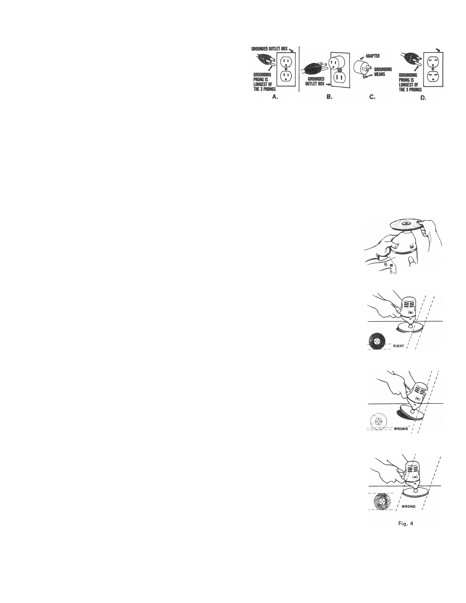
If your unit is for use on less than 150 volts, it has a plug like
that shown in Figure A. If it is for use on 150 to 250 volts, it has
a plug like that shown in Figure D. An adapter, Figures B and C,
is available for connecting Figure A plugs to two-prong recep
tacles. The green-colored rigid ear, lug, etc., must be connected
to a permanent ground such as a properly grounded outlet box.
No adapter is available for a plug as shown in Figure D.
Adapter shown in Figures B & C is Not for Use in Canada.
0«}UNDEO OUTLET BOX
We recommend that you NEVER disassemble the tool or try to
do any rewiring in the electrical system. Any repairs should be
performed only by
B&D
Service Centers or other qualified
service organizations. Should you be determined to make a
repair yourself, remember that the green colored wire is the
“grounding" wire. Never connect this green wire to a “live”
terminal. If you replace the plug on the power cord, be sure to
connect the green wire only to the grounding (longest) prong
on a 3-prong plug.
To start tool, depress trigger: to stop, release trigger. To lock
trigger in
“ON”
position for continuous operation, depress
trigger, push in locking button, and release trigger. To release
locking mechanism and turn off tool, depress trigger and release.
ATTACHING DISCS
1. Place Backing Pad and sanding
disc on spindle of toot.
2. Screw Clamp Washer PARTIALLY
on the spindle.
3. V'/ith one hand, depress the spin
dle lock button and hold the
button down. Grasp the pads and
sanding disc with the other hand
and turn by hand to tighten the
entire assembly (fig. 1).
To remove pads and discs: depress
spindle lock button: grasep the pads
and disc: and turn pad and disc
assembly in opposite direction.
OPERATION
Rg. I
Grasp the control handies firmly and
operate the tool freely without forced
effort or unnecessary pressure. For
maximum efficiency, the tool must
be positioned so that the sanding
disc is at the proper angle to the
work. Fig., 2 (marked “RIGHT”) illus
trates how the tool is tipped slightly
in order to let the maximum amount
of abrasive contact the work without
affecting the smoothness of the sand
ing action. Fig. 3 and Fig. 4 (marked
“WRONG”) show incorrect positions
which allow either too little or too
much abrasive contact. If only the
outer edge of the sanding, disc is
used (as in Fig. 3), a rough cut sur
face will result. If the sanding disc
is pressed flat against the work (as
in Fig. 4), the cutting action will be
irregular and bumpy, and the toot
will be difficult to control.
CLEANING
Blowing dust and grit out of the main
housing by means of an air hose is
recommended and may be done as
often as dirt is seen collecting in and
around the ventilator vents. The
motor should be running while air
is being blown into the air vents.
Fig. 2
Fig.3