Output connections, Aux output, Microphone level output – Bogen CAM User Manual
Page 3: Mic outputs, Other connections, Figure 4 — single connection for increased inputs, L4—1
Attention! The text in this document has been recognized automatically. To view the original document, you can use the "Original mode".
OUTPUT CONNECTIONS
AUX OUTPUT
This output may be used to interconnect equipment with a
high-level, high-impedance input, such as the auxiliary input
of an amplifier or booster. Use single-conductor shielded cable
terminated in an RCA phono plug to connect the output to
other equipment.
MICROPHONE LEVEL OUTPUT
The CAM output can be connected to the microphone input
of another preamplifier or amplifier. Connections are made
with standard microphone cables and appropriate connectors.
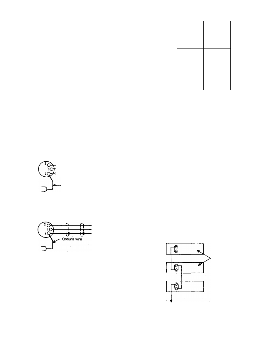
MIC OUTPUTS
Connections
for
high-impedance/low-impedance
un
balanced outputs and low-impedance balanced outputs are
illustrated in figure 3. Use single conductor shielded cable for
unbalanced outputs and two-conductor shielded cable for
balanced outputs, terminated in a Cannon XLR-311 connector,
or equivalent.
Unbalanced Lo-Z or Hi-2 microphone output
Hot lead
Ground
Q.
-M-
L4—1
Ground wire to (-) 28VDC terminal if hum
exists with units connected
Balanced Lo-2 microphone output
Figure 3 — Microphone output connections
OTHER CONNECTIONS
The CAM may be used to increase the number of inputs of
any public address amplifier. Use either the AUX or MIC
outputs of the CAM and connect to the similar input of the
amplifier. See figure 4.
AUX output
§“
i\4
©
AL X input
Bogen C, CT, CTS amplifier
or other PA amplifier
Figure
4
— Single connection for increased inputs
Units may be connected in series to increase the number of
inputs. Connection is made with single-wire shielded cable from
the AUX output of one CAM to the AUX input of the next.
Care must be taken to adjust the AUX and MASTER controls
on units connected this way to arrive at equal levels from all
microphone inputs. See figure 5.
Up to four additional units may be cascade-connected to
provide up to 16 additional microphone outputs. Use two-con
ductor shielded cable and make connections as shown in figure 7.
Connect the AUX output to Bogen C, Ci; CTS or equivalent PA
amplifier.
High or low impedance MIC outputs may be paralleled
directly to supply a MIC input on a following amplifier or
preamplifier. See figure 8.
Note
If hum is ituroduceci when units are connected,
it may he necessary to connect a ground wire
from chassis to chassis. The negative DC supply
terminal is ground on the CA M,
Set masters to maximum
on all except last unit
Combined output
Figure 5 — Series-connected outputs