Grounding, Extension cord, Motor brushes – Black & Decker 44502-02 User Manual
Page 2: Commercial, Industrial use warranty, Attaching hammer tools, Operation, Lubrication, Hammer supplies, Commercial/ industrial use warranty
Attention! The text in this document has been recognized automatically. To view the original document, you can use the "Original mode".
t
4
-
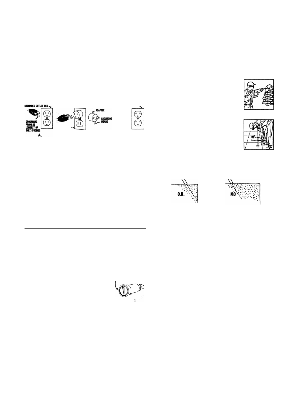
GROUNDING
This tool should be grounded while in use to protect the operator
from electric shock. The tool is equipped with an approved
three-conductor cord and three-prong grounding type plug to fit
the proper grounding type receptacle. The green (or green and
yellow) conductor in the cord is the grounding wire. Never
connect the green (or green and yellow) wire to a live terminal.
If your unit Is for use on less than 150 volts, it has a plug like
that shown in Figure A. If It is for use on 150 to 250 volts, it has
a plug like that shown in Figure D. An adapter, Figures B and C,
is available for connecting Figure A plugs to two-prong recep
tacles. The green-colored rigid ear, lug, etc,, must be connected
to a permanent ground such as a properly grounded outlet box.
No adapter is available for a plug as shown in Figure D. Adapter
shown in Figures B & C is Not for Use in Canada.
a«)U№Q) OUTLET gOK
GftoiMe
OUTLET BOX
/
6R0UNDIN6
PRONG IS
LOHKSTSH^
THE3PR0HGS
B.
c.
D.
We recommend that you NEVER disassemble the tool or try to
do any rewiring in the electrical system. Any repairs should be
performed only by B&D Service Centers or other qualified
service organizations. Should you be determined to make a
repair yourself, remember that the green colored wire Is the
“grounding" wire. Never connect this green wire to a “live"
terminal. If you replace the plug on the power cord, be sure to
connect the green wire only to the grounding (longest) prong
on a 3-prong plug.
EXTENSION CORD
When using the tool at a considerable distance from power
source, a 3-conductor, grounding-type extension cord of ade
quate size must be used for safety, and to prevent loss of power
and over-heating. Use the table below to determine the mini
mum wire size required in an extension cord.
Use only three wire extension cords which have three-prong
grounding-type plugs and three-pole receptacles which accept
the tool's plug. Replace or repair damaged cords.
Ampere rating
Oto
2.10
to
3.5 to
5.10 to
7.10 to
12.1
to
(on nameplate)
2.0
3.4
5.0
7.0
12.0
16.0
Ext. Cable length
Wire Size (A.W.G.)
25 ft.
18
18
18
18
16
14
50 ft.
18
18
18
16
14
12
75 ft.
18
18
16
14
12
10
100
ft.
18
16
14
12
10
150 ft.
16
14
12
12
—
—
200
ft.
16
14
12
10
—
—<
RETAINING SPRING
Fig.
MOTOR BRUSHES
Inspect carbon brushes regularly. First, unplug
the tool, then press together the two prongs
of the Retaining Spring (see Fig. 1) and re
move spring. Unscrew brush cap and remove
brush and spring assembly. Replace when
brushes are worn down to the identifying
letter or groove, or when spring exerts insuf
ficient pressure to hold brush against com
mutator. Keep brushes clean and sliding freely
in guides.
COMMERCIAL/
INDUSTRIAL USE WARRANTY
Black & Decker warrants this product for one year from the
date of purchase. We will repair without charge, any defects
due to faulty material or workmanship. Please return the com
plete unit, transportation prepaid, to any Black & Decker Ser
vice Center or Authorized Service Station listed under “Tools
Electric" in the yellow pages. This warranty does not apply to
accessories or damage caused where repairs have been made
or attempted by others.
Fig. 2
Fig. 3
ATTACHING HAMMER TOOLS
First, swing the Tool Retaining Spring (located in front of the
nose piece) to one side. Insert tool bit into nose piece until
shoulder on tool bit bottoms on nose piece. (NOTE: If tool bit
does not bottom, hold Hammer so that tool bit is touching the
ground, and push the Hammer sharply downward to seat the
tool bit.) Next, swing Tool Retaining Spring back into place so
that ft engages the shaft of the tool ‘bit.
OPERATION
Grasp handle of Hammer with one hand, and
the barrel of Hammer with the other hand
(see Fig. 2). If using Star Drills, grasp Ham
mer handle and the Turning Handle (see Fig.
3). Place tool in working position and depress
trigger. When using Star Drills, swing Turning
Handle in a 180° arc about 30 times per min
ute to prevent binding and to remove cuttings;
exert firm even pressure for best results.
NOTE: Use Dust Shield for all overhead
drilling.
For best demolition performance always place
the end of the bit close to an edge of the
work, breaking the work away piece by piece
(Fig. 4). Trying to break away too large a chunk may cause the
bit to get stuck in the work and may also decrease demolition
rate.
Fig. 4
LUBRICATION
The most important point in keeping your Electric Hammer free-
running and powerful Is regular oiling. Oil cups are located in
the gear case under the switch handle. Oil liberally (several
squirts from the can) after every 3 hours of Hammer operation.
In overhead work, oil Hammer, through the nose piece rather
than through the oil cups. Excess oiling will cause some leakage
around the tool shank, but this does no damage and Hammer
will clear Itself rapidly in operation.
Black & Decker Special Hammer Oil (See Hammer Supplies,
this booklet) has special qualities for adhering to high speed
working parts and will greatly prolong the life of the tool. In an
emergency, use high grade SAE No. 30 Oil.
In from 30 days to 3 months, depending upon use, your Ham
mer sould be sent to the nearest B&D Service Branch for a
complete cleaning and replacement of lubricant In the gear case.
Your Hammer will be returned to you completely cleaned and
adjusted with new parts installed where necessary.
HAMMER SUPPLIES
Cat. No. 51315 Special Hammer Oil, 1 pint can
Cat. No. 60541 Hammer Gear Grease, 1 lb. can
Cat. No. 7276 Drift Key (To remove tapered shank bits from
chuck)
Cat. No. 10909 Tool Retaining Spring, & 1" Hammers
Cat. No. 21750 Tool Retaining Spring, IVi" Hammer
Cat. No. 17746 Dust Shield for Wrenches Nos. 22587, 23806,
and Chuck Head 22510.
Cat. No. 17747 Dust Shield for Wrenches Nos. 22749, 22854