Charging procedure, Chuck & key, Trigger switch & control button – Black & Decker 1941 User Manual
Page 2: Lock-‘‘off, Forward, Reverse, Charging the power pack, Operation, Drilling (figúrelo)
Attention! The text in this document has been recognized automatically. To view the original document, you can use the "Original mode".
IMPORTANT CHARGING NOTES
1. Longest fife and best performance can b© obtained if the
batteries are charged when the air temperatyr# is aboyt
75®F. 00 NOT charge the batteries In an air teroperatyre
below
4
-
40
®F or above -f 105®F. This Is importarit and will
prevent serloys daimag© to the batteries.
2 When yoy charge yoyr power pack for the first time, or
after prolonged storage, it will only accept about an 80%
charge. However, after several charge and discharge cycles,
the batteries will be up to full capacity.
3. While charging, the Charger may hum and become warm
to touch. This is a normal condition, and does not indicate
a problem.
4. If the batteries do not charge properly — (1) Check current
at receptacle by plugging in a lamp or other appliance, (
2)
Check to see if receptacle is connected to a light switch
which turns power off when you turn out the lights. (3) Move
charger and power
pack to a surrounding air temperature
of approximately 75^' F. In an extremely warm environment,
the power pack may be too hot to permit fast charging. (4)
If the receptacle and temperature are o.k., and you do not
get proper charging, take or send the tool
and^charger to
your local service center. See “TOOLS, ELECTRIC” in
yellow pages.
5. The power pack should be recharged when it falls to pro*
duce^^sufficient power on jobs which were easily done pre
viously. DO NOT CONTINUE to use under these conditions.
Repeat the charging procedure.
6. If, after repeated use, your power
pack does not take a full
charge, and produces operating time less than normal, It
may not be caused by faulty batteries. If you use the power
pack repeatedly for only a few minutes and then charge It,
the batteries build up a resistance to taking a full charge.
This resistance results In reduced operating time.
The batteries can be restored to their original power and
life by fully charging and then completely using up the
charge several times. This will recondition the batteries to
deliver
maximum
performance.
FOR REPLACEMENT OR FOR ADDITIONAL
POWER PACKS OR CHARGERS, ORDER:
No. 98003 Power Pack (
1-hr. charge)
No. 98010 Charger (
1-hr. charge)
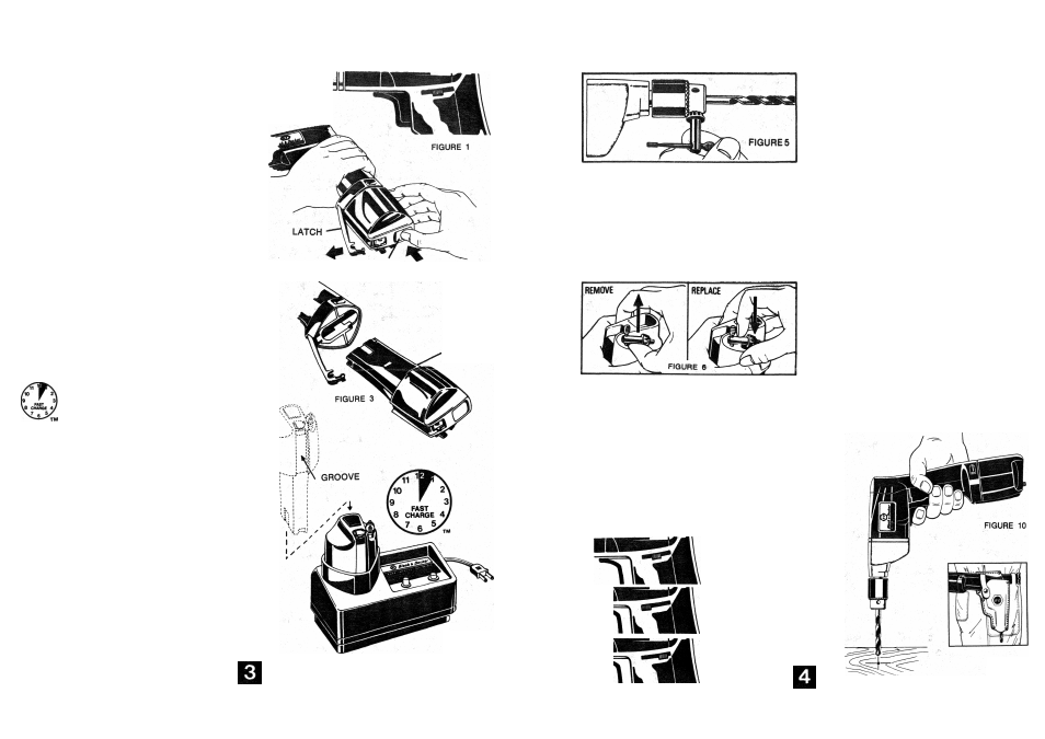
CHARGING THE POWER PACK
CHARGING PROCEDURE
1.
Move Switch Control Button to the center of Its slot to
LOCK Trigger Switch “OFF" {Figure 1).
2.
Remove Power Pack from
Tool Handle by first pressing
Release Button (Figure 2). The Latch will spring open and
allow Power Pack to be withdrawn from handle (Figure 3).
3. Place the Power Pack in the Charger as shown in Figure 4.
Note that groove in Power Pack faces front. Plug in Charger.
4. Press button momentarily until light turns “ON". Your Power
Pack is now on charge.
5. In about an hour the light will turn “OFF". Charging is now
complete and your Power Pack is ready for use.
6. When charging is completed, unplug Charger, lift Power
Pack from Charger and insert Power Pack into tool handle.
Press latch over end of Power Pack until it snaps into the
locked position.
MOTE: If the Power Pack has become warm in use, and is
placed in the charger still warm, the light will not go on and
charging will not begin immediately when the button is pressed.
However, after you press the button you can leave the charger.
As the Power Pack cools down, the light will turn on and charg
ing will begin automatically. ALSO SEE INSTRUCTIONS FOR
NO. 98010/91-005 FAST CHARGER PACKED WITH UNIT.
RELEASE
BUTTON
FIGURE 2
POWER
PACK
FIGURE 4
TM — Trade Mark of Black & Decker
OPERATION
CHUCK & KEY
Turn chuck
collar to open chuck jaws. Place bit in chuck as far
as it will go. Tighten chuck collar by hand. Place chuck key
In
each of the three holes, and tighten in clockwise direction
(Figure 5). It's important to tighten chuck with all three holes
to prevent
bit slippage. To release bit, turn chuck key
counterclockwise in just one hole, then loosen chuck by hand.
When not in use, the chuck key can be stored in the end of the
power pack. To remove the key,
place thumb as shown in
Figure
6 and push key firmly upward out of its holding socket.
To
replace key, push key's handle firmly and completely down
into the socket (Figure
6).
TRIGGER SWITCH & CONTROL BUTTON
The Drill is turned “ON" and “OFF" by pulling and releasing
the Trigger Switch. However, the Trigger can be locked "OFF’
by positioning the Switch Control Button in the center of its
slot (Figure 7). This position should be used to prevent the
Trigger from being accidentally pressed when the tool is not
in use, when attaching or removing the Power Pack, when
attaching or changing accessories, and when cleaning or serv
icing the Drill.
For normal use, the Switch Control Button should be in the
FORWARD position (Figure
8)»
Use the REVERSE position (Figure 9) for smoothly withdrawing
bits that bind in the hole. When moving from FORWARD to
REVERSE, or vice versa, always release the trigger first as the
control button will not move when the trigger is depressed.
Move the control button to FORWARD before starting to drill
again.
LOCK-‘‘OFF”
FIGURE 7
FORWARD
FIGURE 8
REVERSE
FIGURE 9
1. Lock Trigger Switch "OFF” with switch control button when
attaching or changing bits or accessories.
2.
Use sharp drill Wti only. For WOOD, use drill bits,
spade bits, power auger bits, or hole saws. For METAL, use
high-speed steel twist drift bits. For MASONRY, such as
brick, cement, cinder block, etc., use carbide-tipped bits,
3.
Be sure the material to be drilled is anchored or clamped
firmly. If drilling thin material, use a wood “back-up" block
to
prevent damage to material.
4. Center-punch an indentation at the point to be drilled. This
will overcome
tendency of bit to slip around on a smooth
surface. Place the tip of bit in indentation and turn motor
“ON."
5.
Always apply pressure in a straight line with the bit. Use
enough pressure to keep drill biting, but do not push hard
enough to
stall motor or deflect bit. To minimize stalling on
breaking through the material, reduce pressure on drill
and
ease the bit through last part of hole.
6. Hold drill firmly to control the twisting action of the drill.
DRILLING (Figúrelo)
DiliLliG IN WOOD
Holes in wood can be made with the same twist
drill bits used
for metal or with wood augers. These bits should be sharp and
should be pulled out frequently when drilling to
clear chips
from the flutes. Work that is apt to splinter should be backed
up with a block of
wood. Let up on the pressure just before
the tip cuts through, this will
give a good clean hole.
DRILLING
IN
METAL
Use a cutting lubricant when
drilling ferrous metals. The ex
ceptions are iron and brass which should be drilled dry. The
cutting lubricants that work best are sulphurized cutting oil or
lard
oil; bacon grease will also serve the purpose. Aluminum
is best drilled with turpentine or kerosene.
LEATHER HOLSTER
To
add even more to the convenience features of your Cordless
Drill, an accessory Leather Holster is available. This Holster
fastens to your belt and keeps the Drill handy and ready for
work.
It also frees both hands when you are not actually using
the
tool. Order;
Cat. No. 98-004/91-012 Leather Holster (Figure 11)
FIGURE 11