Bogen CA21 User Manual
Observe color code: ca-15b, Once, the switch signals an administrator to, Through
Attention! The text in this document has been recognized automatically. To view the original document, you can use the "Original mode".
INI
C O M M U N I C A T I O N S , I N C .
CALL/EMERGENCY SWITCHES
MODELS CA-15B, CA-16A & CA21
The Bogen CA15B is a momentaiy, rocker-type call switch
designed for use in Bogen COMMUNTTEL® 2A and MULTI-
COM™ 2000 communication systems. When pushed and released
once, the switch signals an administrator to
establish a call
through
a two-way speaker (The switch may also function as a single-push
emergenty switch in the MULTTCOM 2000 s^em, when the staff
station is configured for level 3 access.) When pushed and released
four times, the switch initiates an
emergency
call at the administra
tive station.
The Bogen CA-16A is a momentaiy, rocker-typ>e call switch
designed for use in the Bogen COMMUNTTEL 2A. ^em. The
switch functions the same as the CA-ISB and has an added privacy
feature, which prevents monitoring from the administrative sta
tion. The
privacy
position does not interfere
with
the
ability
of
the
administrative station to call the staff station; however, the privacy
switch must be released for communications.
The Bogen CA-21 is a mommtaiy, rodeer-type call switch
designed for use in the Bogen MULTICOM 2000 system. The
switch functions the same as the CA15B and has an added privacy
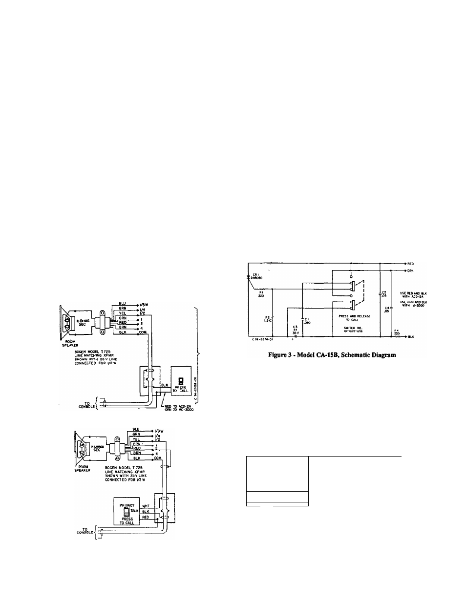
Figure 1 - Model CA-15B, Connecting Diagram
Figure 2 - Model CA-16A & CA-21, Connecting Diagram
feature, wdiich prevents monitoring from the administrative sta
tion. The privacy position does not interfere with the ability of the
administrative station to call the staff station; however, the privacy
switch must be released
for oommuiucations.
All call switches are designed for flush mounting in standard
single-gang outlet boxes. Figures 1 and 2 illustrate the proper
connections. The shield must not be grounded to the building
ground at the outlet box or the speaker. (See appropriate system
manual.)
Caution
Observe color code: CA-15B
—
red fca-anmmàator line
in COMMUNITY 2A systems or orange for annunciator
line in MULTICOM2000systems.
Figure 4 - Model CA-ltiA, Schematic Diagram
- - C I
• '.05
6
PRESS AND
RELEASE TO CALL
SWITCH NO.
TALK
ei'003-0A4
(
unused
contacts
NOT SHOWN 9
VsA--------- - - ----------- C
fli
!»
B7fl-6372-0(
Figure 5 - Model CA-21, Schematic Diagram
COMMUNICATIOlua, INC.
50 SPRING STREET, P O. Bo. 575
RAMSEV. N J 07106 (?011931-8600
54-S9ia-01 6912 Printed In U.S.A.