Maintenance, Changing clutches (fig. ?) for versa-clutch only – Black & Decker Scrugun 2033-10 User Manual
Page 4
Attention! The text in this document has been recognized automatically. To view the original document, you can use the "Original mode".
VERSA-CLUTCH FOR DRIVING A
WIDE RANGE OF FASTENERS
RPM
0-1200
NOMINAL CAPACITY
SELF THREAD SHEET
WOOD
LAG
DRILL
CUTTING METAL MACHINE
SCREWS
SCREWS
SCREWS
SCREWS SCREWS SCREWS
#12
1/4" w/pilot hole
1/4"
1/4"
3/16" CRS
1/4"
1 /4"
1. Install proper fastener driving accessory and set screwdriver for
correct rotation.
2. Adjust clutch setting. See Fig. 4.
3. Place fastener in accessory, contact workpiece and apply
pressure to seat fastener keeping clutches engaged.
4.
Upon fastener seating the clutches will ratchet. Disengage
screwdriver from fastener.
NOTE: With Versa-Clutch the operator has the ability to "override”
clutch ratchet if a fastener hits a wood knot, variable hardness in
steel workpieces or incorrect pilot holes. Increased operator
pressure will usually cause the clutches to "pick-up” and continue to
seat the fastener. Further, a quick twist of the collar will change the
clutch setting to overcome most driving difficulties and will provide
for immediate change in torque output giving the operator option to
drive a range of fastener sizes.
MAINTENANCE
CLEANING
With the motor
running,
blow
dirt
and dust out of
all
air vents with
dry air
at least once a week. Wear safety glasses when performing
this.
Exterior
plastic parts may be cleaned with a damp
cloth
and mild
detergent.
Although these parts are highly solvent resistant, NEVER
use solvents.
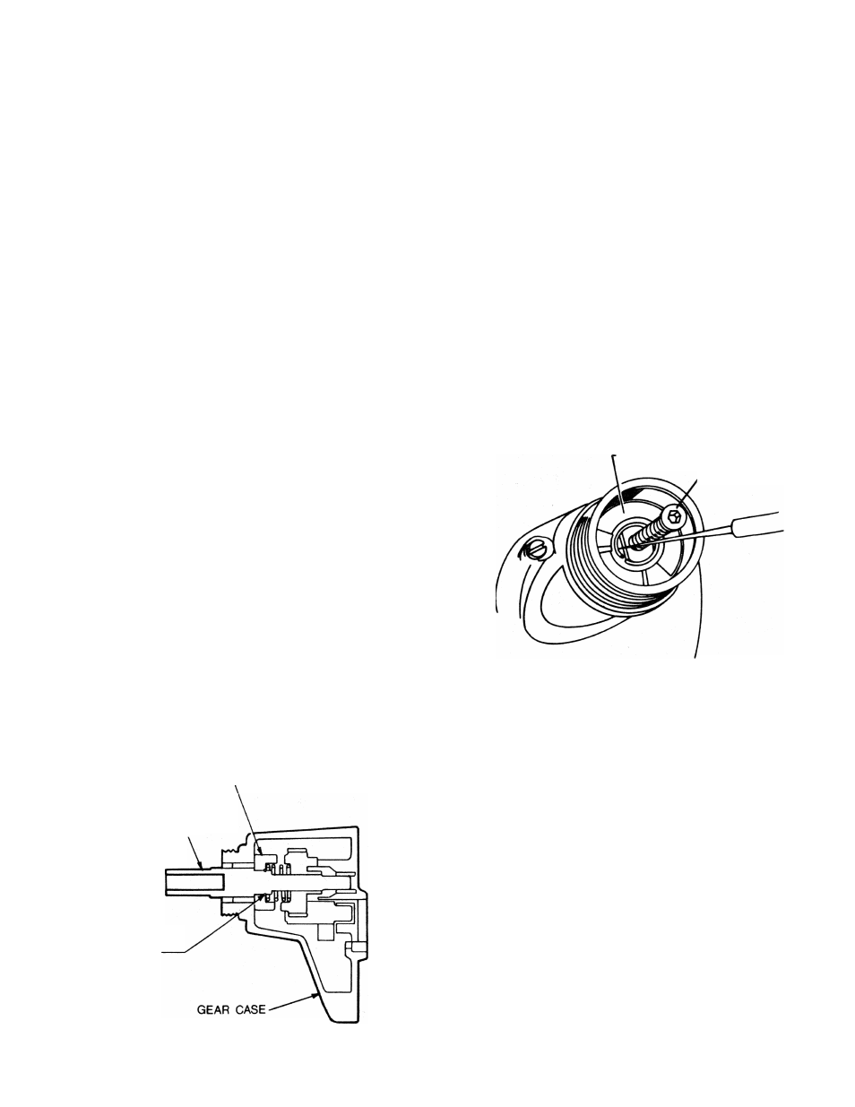
CHANGING CLUTCHES (Fig. ?) FOR VERSA-CLUTCH ONLY
1. Remove clutch housing by unscrewing in direction of arrow
(left hand thread).
2. Clamp tool or clutch housing in a resilent clamp.
3. Remove round clutch retaining rings ■ with a very small
screwdriver or sharp pointed tool.
4. Install new clutches and new retaining rings.
NOTE:
If
the output spindle slides toward Inside of gear case,
remove dead spindle spring and thread a 5/16" -18 bolt or
cap.screw into end of spindle and lift up to expose retaining
ring groove. Re-assemble dead spindle spring allowing no
more than 1/4" projecting from end of spindle.
5. Relubricate clutches. (See lubrication'
CLUTCH FACE
5/16"-18 SCREW
Figure 7
CHANGING CLUTCHES (Fig. 8) FOR POSITIVE CLUTCH & DRYWALL UNITS ONLY
CLUTCH
OUTPUT
SPINDLE
RETAINING
RING
1. Remove three gear case screws from front and disassemble
^ gear
case.
2.
Clamp output spindle
In
a resilient clamp.
3. Remove round clutch retaining rlng^ with a very small
screwdriver or sharp pointed tool.
4.
Install a new clutch and
retaining ring.
5.
Relubricate clutches and gearing. (See lubrication).
Figure 8