Changing, P.t.l safety rules for stationary power tools, Grounding – Black & Decker 4335 User Manual
Page 2: Lubrication, Motor, Wheels, Accessories, Additional grinder safety rules, Io" bench grinder
Attention! The text in this document has been recognized automatically. To view the original document, you can use the "Original mode".
P.T.L SAFETY RULES
FOR STATIONARY
POWER TOOLS
1. KNOW YOUR POWER TOOL. Read the owner’s manual
carefully. Learn its .application and limitation, as well
as the specific potential hazards peculiar to this tool.
2. KEEP GUARDS II PLACE and in working order.
3. GROUND ALL TOOLS. If tool is equipped with three-
prong plug, it should be plugged into a three-hole
electrical receptacle. If an adapter Is used to accom
modate a two-prong receptacle, the adapter wire must
be attached to a known frouni. Newer remove the
third prong.
4.
REMOVE ADJUSTING * KEYS AND WRENCHES. Form
habit of checking to see that keys and adjusting wrenches
are removed before turning on tool.
5. KEEP WORK AREA CLEAN. Cluttered areas and benches
invite accidents.
6
.
AVOID DANGEROUS ENVIRONMENT. Don’t use power
tools in damp or wet locations. Keep your work area
welt illuminated.
7.
KEEP CHILDREN AWAY. All visitors should be kept a
safe distance from work area.
8.
MAKE WORKSHOP KIDPROOF—with padlocks, master
switches, or by removing starter keys.
9. DON’T FORCE TOOL. It will do the job better and be
safer at the rate for which it was designed.
10. USE RIGHT TOOL. Don’t force tool or attachment to
do a job it was not designed for.
11. WEAR PROPER APPAREL. No loose clothing or jewelry
to get caught in moving parts.
12.
13.
14
.
15.
16.
17.
18.
USE SAFETY GLASSES. Also use face or dust mask if
cutting operation is dusty.
SECURE WORK. Use clamps or a vise to hold work,
when practical. It’s safer than using your hand, frees
both hands to operate tool.
DON’T OVERREACH. Keep your proper footing and
balance at all times.
MAINTAIN TOOLS IN TOP CONDITION. Keep tools
sharp and clean for best and safest performance. Follow
instructions for lubricating and changing accessories.
DISCONNECT TOOLS before servicing and when chang
ing accessories such as blades, bits, cutters.
USE RECOMMENDED ACCESSORIES. Consult owner’s
manual. Use of improper accessories may be hazardous.
AVOID ACCIDENTAL STARTING.
off before plugging in cord.
Make sure switch is
GROUNDING
These units are equipped with an outlet box
mounted on the back of the unit for permanent
wiring, as required by Underwriters Laboratories.
Wiring diagrams are pasted to the underside of
the base. To insure proper wiring & “grounding”
of tool, have connection made by a qualified
electrician.
LUBRICATION
This tool is equipped with lubricant sealed ball
bearings which require no further lubrication for
the life of the bearing.
MOTOR
Four pole capacitor start induction motor,
rel cage rotor.
Squir-
Cat
Rated
RPi
No. Phase HP
Cycles
@ 115 V.
Mo Load
Voltage, A.C.
4330 1
1
50/60
14.6/13
1500/1800
115 Volts
4330-01 1
1
50/60
14.6/13
1500/1800
220 Volts
4335 3
1
50/60
14.6/13
1500/1800
220/440
Reconnectable
CHANGING
WHEELS
Remove 4 screws holding wheel guard cover.
Loosen and remove hexagon nut. (Nut on left
wheel has left hand threads, nut on right wheel
has right hand threads) and clamp washer. Re
move wheel. To reassemble, reverse above steps.
Do not overtighten nut. Wheel size 10" O.D.,
3
/
4
" I.D., 1" Width.
ACCESSORIES
No. 34575 One Shatter-Proof Eye Shield . . . Fastens per
manently to Bench Grinder. Adjusts quickly to various posi
tions to suit operator. Not illuminated. (Replacement glass,
No. 34576).
No. 19115 Cutter Wheel Dresser . . . Has spare set of cutter
wheels. Dresses wheels quickly for fast grinding.
No. 21961 Diamond Dresser . . . Produces an accurate,
smooth face for finish grinding.
No. 53536 Pedestal . . . Holds grinder at convenient height.
Has detachable water pot. Height: 31%"; Base: 16 square.
Grinding Wheels (10" Diam. x 1" Face x %" Hole):
No. 10274 Specification A24Q6V, Type 1
No. 10275 Specification A46N6V, Type 1
Wire Wheel Brushes (10" Diam. x 1%" Face x %" Hole:
No. 21407
.014 Wire Diam. (30 Gage)
No. 27012
.0118 Wire Diam. (33 Gage)
Cotton Buffing Wheels (10" Diameter x ^/
4
" Hole):
No. 26873
%" Wide
No. 26876
V4" Wide
CAUTION:
Recommended accessories for your Bench
Grinder are listed above. The use of any other accessory
might be more hazardous.
ADDITIONAL GRINDER SAFETY RULES
1. Always wear safety glasses or other eye protection when
4.
operating this tool, and eye shields, mounted on the
wheel guards, are strongly recommended.
2. Replace a cracked wheel immediately. Handle grinding
5.
wheels carefully to avoid bumping or dropping. DO NOT
use a grinding wheel that has been dropped. Before
using, inspect each grinding wheel for cracks or flaws
6.
and if these are evident, discard the wheel.
Before mounting a new wheel, be sure that it is marked
with an R.P.M. that is the same as, or higher than, the
no-load speed of the grinder as marked on the name
plate. Do not overtighten wheel nut. Use only flanges
furnished with this grinder.
Never start a grinder with anyone, including the operator,
standing in line with the wheel. After installing a replace
ment wheel, stand to one side and allow it to revolve
freely for about one minute.
Do not grind on the sides of grinding wheels unless they
are the special wheels designed specifically for this
purpose.
Use of any other accessory or attachment other than
those specified might create a hazard for the operator.
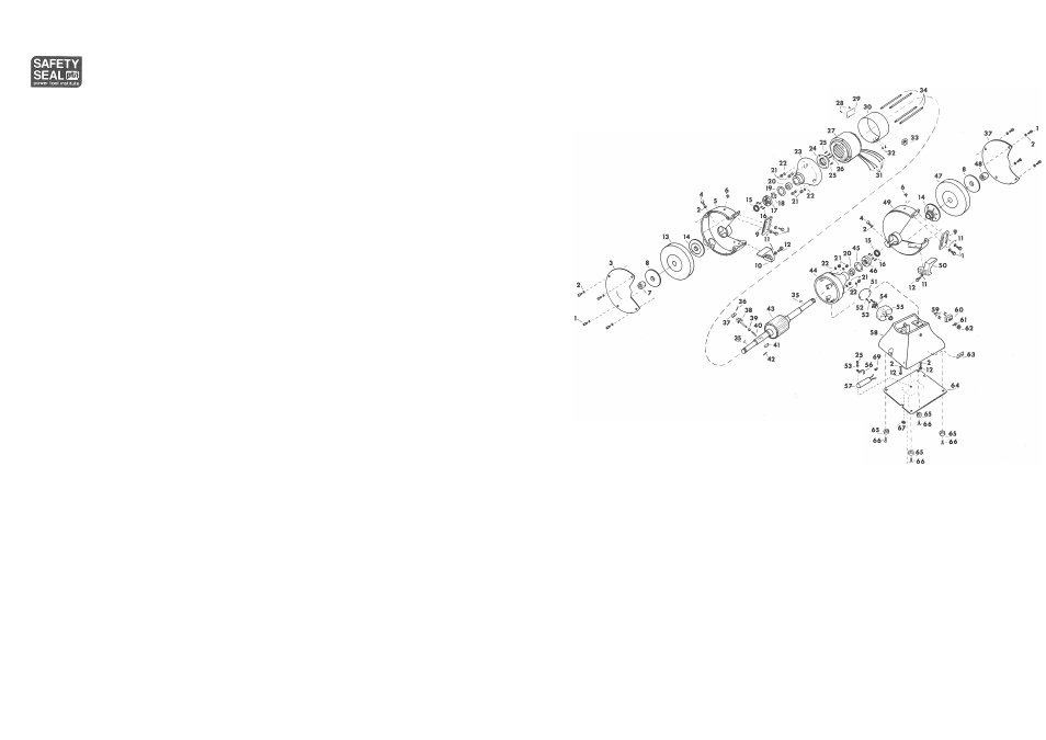
IO" BENCH GRINDER
Cat- No. 4330, TY. 1,11S¥, 1 Ph.
Cat. No. 4330-01, TY. 1, 220V, 1 Ph.
Cat. No. 4335, TY. 1, 220/440V, 3 Ph.
1
11467
5/16-24
X
% Hex head screw (12)
2
393
5/16 Lock washer (12)
3
982372
Guard cover (2)
4
6947
5/16-24 X 1 Hex head screw
(2)
5
982370
Wheel guard
6
13345
V
a
-28
X
Vz
Round head machine
screw and washer (2)
7
10257
3
/
4-10
Hex nut (L.H.)
8
982064
Outer clamp washer (2)
9
15726
Spark shield (2)
10
15709
Tool rest (L.H.)
11
801
Flat washer (6)
t36
16623
Pin
12
5531
5/16-18
X
1 Hex head screw (4)
t37
34246
Brush
13
10274
Grinding wheel (coarse)
t38
982954
Brush
carrier
14
982063
Inner clamp washer (2)
t39
17022
Sleeve
15
15711
Felt washer (2)
■ t40
17020
Brush spring
16
367
10-32 x % Fillister head
t41
17024
Weight
machine screw (8)
t42
17021
Pin
17
15705
Bearing cap
43
982952
Rotor
18
15717
Spring washer
44
19628
End
housing
19
15722
Gasket
45
19624
Gasket
20
15740
Bali bearing (2)
46
15706
Bearing cap
21
405
1
/
4-20
Hex nut (8)
47
10275
Grinding wheel (mediunr
22
416
1/4
Lock washer (8)
48
10256
?4-10
Hex nut (R.H.)
23
15698
End housing
49
982371
Wheel guard
t24
982927
Centrifugal switch (stationary)
60
15710
Tool rest (R.H.)
t25
375
10-32
X 3/8
Round head screw (3)
51
34521-01
Cover plate
t26
20406
6-32
X
3/16 Terminal screw (2)
52
374
10-32 X 5/8 Round head
27
19664-61
Stator 115v. 1 phase
machine screw (2)
19664-65
Stator 220v. 1 phase
53
417
#10
Lock washer (3)
19664-75
Stator 220/440V. 3 phase
54
54691
Cord clamp and
nut
28
14002
Rivet (2)
55
34522-01
Outlet box
29
61466
Nameplate
t56
19325
Condenser clamp
30
15719
Stator Band
t57
30390
Condenser
31
34289
Lead terminal (6)
58
995935
Base
32
22977
Drive screw (2)
59
2379
Terminal screw (4)
33
58122
Hex sticker
60
it36965
Switch (single phase)
34
982977
Stud (4)
I
25920
Switch (3 phase)
35
26587
Woodruff key (2)
61
19326
Indicating plate
t985202
Centrifugal switch (rotating)
62
24701
Hex nut
includes items 36 - 42
63
72418
Caution Sticker
64
15712
Base plate
65
15723
Foot (4)
66
372
1
/
4-20
X
3/j. Round head machine
screw (4)
67
406
10-32 Hex nut
68
57314
Wiring diagram label 1 phase
all voltages
69
67315- 01 Wiring diagram label 3 phase
220 volts
67316- 01 Wiring diagram label 3 phase
440 volts
32114 Connector
Special part not shown for 3 phase
grinders, No. 4335
982318
Insulator (2) (3 phase only)
(switch)
Connection Diagrams
f45699
Connection Diagram
(single phase)
45700-01 Connection Diagram (3 phase)
37485
Locking Ring for #36965 switch
only (single phase only)
fOmit for 3 phase
BULLETIN No. 2928-1