Additional, Operating, Instructions – Black & Decker ELU 3375 User Manual
Page 4: Double insulation, Extension cords, Switch, Fv'x m, Additional operating instructions
Attention! The text in this document has been recognized automatically. To view the original document, you can use the "Original mode".
TRIGGER SWITCH
Additional
Operating
Instructions
PRECAUTIONARY
INSTRUCTIONS
1. CAUTION—Blades are
extremely sharp. Avoid body
contact.
2. Read owner’s manual thoroughly
before using tool.
3. Voltage must agree with specific
data on the nameplate.
4. Be sure the switch is in “OFF”
position before connecting tool to
power supply.
5. Switch tool “OFF” immediately if
tool should become jammed in
work.
6. Be sure tool is disconnected from
power source when cleaning,
adjusting, or doing maintenance
on the tool.
7. Planer should be properly set and
adjusted before turning unit on.
8. Use specified replacement parts
only.
9. Maintain tool with care. Follow
instructions for changing blades.
10. Store tool in a clean dry place
after disconnecting from power
source.
11. Do not force tool, allow tool to
perform as it was designed. Use
only sharp blades.
12. Do not allow visitors to approach
work area, especially children.
13. Do not cover the air vents on the
tool. Vents must be kept open for
motor cooling.
14. Do not leave tool unattended
without disconnecting from power
source.
15. Do not yank cord when
disconnecting tool from power
supply.
16. Do not carry the tool by power
cord.
17. Do not carry planer with your
finger on the switch.
18. Do not lay tool down on shoe
when the blades are exposed.
19. Do not allow planer blade to
contact metal objects. This may
chip or damage blades.
NOTE—Do not use chipped or
damaged blades.
20. Do not obstruct side chip chute.
SHOE ADJUSTMENT
KNOB
FRONT BORE
21. Always use fence unless surface
planing. Use extreme caution,
stay clear of drive belt and cutter
location.
22. Turn off tool immediately after
finishing cut.
SAVE THESE INSTRUCTIONS
Double Insulation
Your unit is DOUBLE-
INSULATED to give you added
safety. This means that it is
constructed throughout with TWO
separate “layers” of electrical
insulation or one DOUBLE thickness
of insulation between you and the
tool’s electrical system.
Tools built with this insulation
system are not intended to be
grounded. As a result, your tool is
equipped with a two-prong plug which
permits you to use extension cords
without concern for maintaining a
ground connection.
NOTE; DOUBLE INSULATION
does not take the place of normal
safety precautions when operating
this tool. The insulation system is for
added protection against injury
resulting from a possible electrical
insulation failure within the tool.
CAUTION: When servicing all
tools. USE ONLY IDENTICAL
REPLACEMENT PARTS. Repair or
replace damaged cords.
Extension Cords
Double insulated tools have 2 wire cords, and can be used with 2 wire or 3
wire extension cords. Only round jacketed extension cords should be used, and
we recommend that they be listed by Underwriters Laboratories (U.L.). If the
extension will be used outside, the cord must be suitable for outdoor use. Any
cord marked as outdoor can also be used for indoor work. The letters “WA” on
the cord jacket indicate that the cord is suitable for outdoor use.
An extension cord must have adequate wire size (AWG or American Wire
Gauge) for safety, and to prevent loss of power and overheating. The smaller
the gauge number of the wire, the greater the capacity of the cable, that is 16
gauge has more capacity than 18 gauge. When using more than one extension
to make up the total length, be sure each individual extension contains at least
the minimum wire size.
To determine the minimum wire size required, refer to the chart below;
CHART FOR MINIMUM WIRE SIZE (AWG) OF EXTENSION CORDS
FENCE
ROD TIGHTENING
KNOB
NAMEPLATE
RATING-AMPS
TOTAL EXTENSION CORD LENGTH-FEET
25
50
75
100
125
150
175
200
0
-
10.0
18
18
16
16
14
14
12
12
10.1
-
13.0
16
16
14
14
14
12
12
12
13.1
-
15.0
14
14
12
12
12
12
12
—
Before using an extension cord, inspect it for loose or exposed wires,
damaged insulation, and defective fittings. Make any needed repairs or replace
the cord if necessary.
lb
Your ELU tool IS powered by an
ELU-built motor. Be sure your power
supply agrees with the nameplate
marking.
Volts 50/60 Hz or “AC only”
means your tool must be operated
only with alternating current and never
with direct current.
Voltage decrease of more than
10% will cause loss of power and
overheating. All ELU tools are factory
tested; if this tool does not operate,
check the power supply.
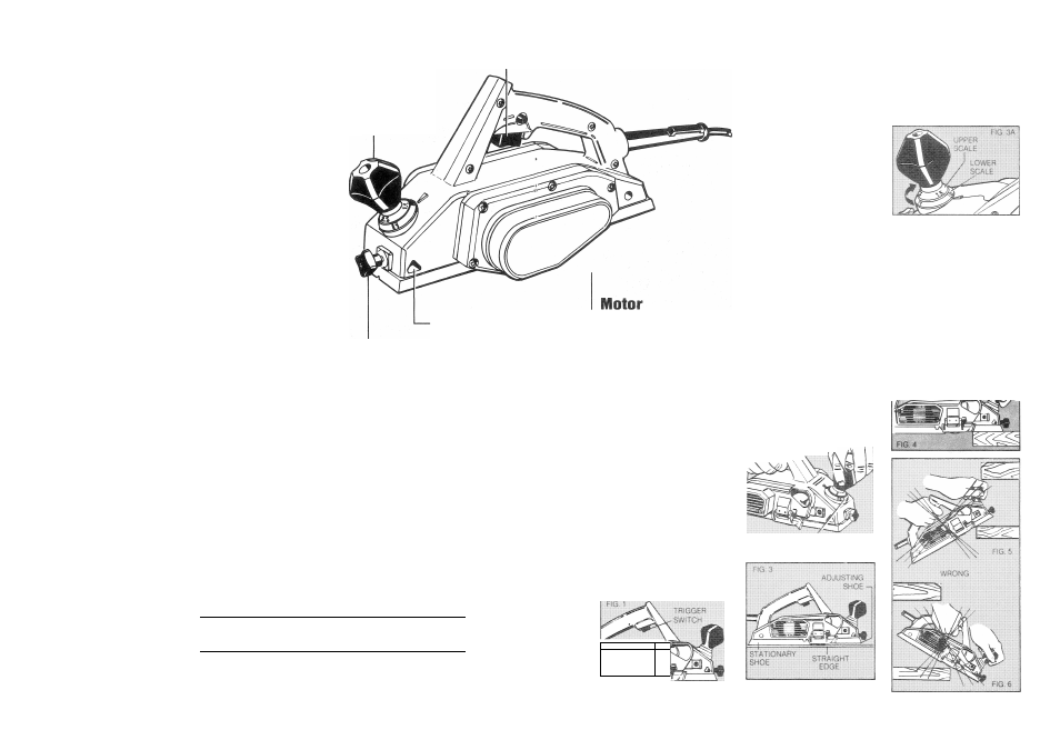
Switch
Always pick up your planer by the
handle before depressing the switch.
NOTE; Always remember to keep free
hand away from bottom of planer. The
planer IS started by depressing the
trigger in the handle. To turn the
planer off, release the trigger (Fig. 1),
Allow time for the blades to stop
turning before setting the tool down.
To lock the planer “ON” squeeze
the trigger and hold it while you press
in the trigger locking button in the
handle next to the trigger. Hold the
locking button in while you release the
trigger and the tool will continue to
run. To release the trigger lock,
squeeze and release the trigger once.
------
UNPLUG PLANER
The adjustment of the desired
depths is accomplished by turning
shoe adjustment knob.
First, set the planing depth to zero
by placing a straight edge along the
bottom of the tool and adjusting the
front shoe until the front and stationary
shoes are of equal height (Fig. 3), (At
this point, no light will pass between
the shoes and the straight edge.)
When both the adjustable shoe
and the stationary shoe are even, the
adjusting knob should read zero on
the lower scale, as shown in Figure
3A. From that starting point, rotate the
adjusting knob clockwise to raise the
adjustable shoe. Each full revolution of
the adjusting knob raises the shoe
1/16” (1.5 mm) and the scale on the
knob is marked in .5 mm graduations.
On the first revolution of the knob,
read the graduations on the bottom of
the knob and on the second
revolution, read the upper graduations,
as shown in Figure 3A. When you
have adjusted the planer, practice on
a piece of scrap wood until you are
comfortable with the tool.
SHOE
f
KNOBJ
fV'X M
With one hand holding the handle,
place the front shoe on the work,
making certain blades are not
touching the work. Put pressure on the
handle so that the front shoe is
absolutely flat on the work (Fig. 4).
Start to plane with motor running at full
speed. NOTE; Several shallow
passes will produce a smoother
surface than one deep one.
In the beginning and in the end of
planing, be especially careful to keep
your planer flat on the work (Fig. 5 & 6).
A
■
. .
■/.