After-sales service – AEG EL User Manual
Page 7
Attention! The text in this document has been recognized automatically. To view the original document, you can use the "Original mode".
3. After-sales service
Complaints which arise through failure to observe these instructions cannot be
acknowledged!
Any faults which are not mentioned in this instruction manual must be referred to our af
ter-sales service department.
The list of addresses can be obtained from the guarantee conditions which accompa
ny the unit.
It is essential that you state the model designation and the E-Number given on the na
meplate in order to avoid unnecessary queries.
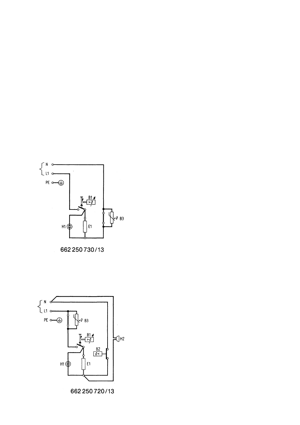
Wiring diagram for Thermofix E
Q = ON button for B 1
H1 = Indicating lamp,
H 2 = Buzzer
E = Heating element
X = Terminal board - 2-pole - inside appliance
B1 = Temperature selection limiter
B2 = Steam regulator
B3 = Temperature control
Wiring diagram for Thermofix ELyGL
13