Motor, Commutator and brushes, Grounding: o – Black & Decker Type 1A User Manual
Page 2: Cable, Safety precautions, Switch, Lubrication, Attaching abrasive paper
Attention! The text in this document has been recognized automatically. To view the original document, you can use the "Original mode".
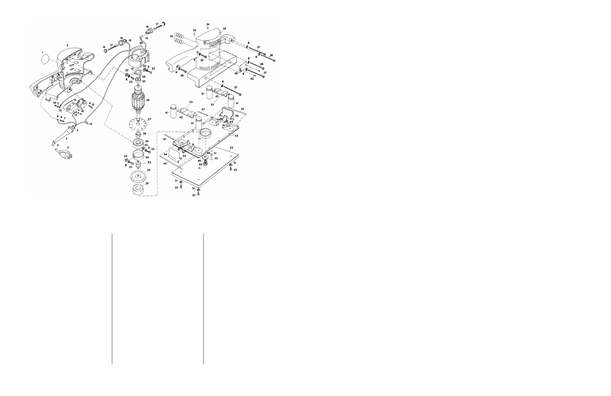
PARTS IDENTIFICATION
4015 H.D. FINISHING SANDER, 3.0 AMPS., 10,000 O.P.M.
Index
Index
Index
No.
Part No,
Part Description Quantity
No.
Part No. Part Description
Quantity
No.
Part No. Part Description Quanti^
1
57005
¡dent sticker
1
19
46212-01 lead terminal
2
38
65393
#8-32x2% FH screw
2
2
61037
motor housing
1
20
59320-71 field (120V)
1
39
975002
nameplate
1
3
36478
attach, plug (120V)
1
59320-73 field (150V)
1
40
3041
drive screw
2
37140
attach, plug (150-250V)
1
59320-95 field (lOOV)
1
41
66181
flexible post
4
4
36480-98 cord & plug (includes
59320-75 field (220V)
1
42
65427
post spacer; includes
item 3) (120V)
1
21
61138
bearing retainer
1
item 55 (2)
2
37142
cord & plug (includes
22
61137
clamp
4
43
58871
base plate
1
item 3) (150-250V)
1
23
1789
#8-32 X
1/2
FH screw
4
(includes 44, 45, 46,
47)
5
24288
cord protector
1
24
30611
rubber plug
3
44
58874
spring
2
6
8033
cord clamp
1
25
67140
ball bearing
1
45
58897
bumper
2
7
7895
#8-32
X
% RH screw
1
26
89559-31 armature 120V
1
46
58815
clamp
2
8
418
#8 lockwasher
12
89560-33 armature 150V
1
47
67374
roll pin
2
9
1747
lead terminal
1
89560-35 armature 220V
1
48
5927-01
washer
1
10
20404
#5-40 x
%2
term, screw
2
89559-55 armature lOOV
1
49
416
% lockwasher
1
11
1991
#6 lockwasher
2
27
58814
fan
1
50
10584
%-28x% RH screw
1
tl2
26192
lead terminal
2
28
58876
spacer
1
51
417
#10 lockwasher
4
13
49352
switch 100-120V
1
29
54301
ball bearing
2
52
34935
#10-32 X
%2
screw
4
62051
switch 150-250V
1
30
61139
bearing retainer
1
53
59998
base plate & pad
1
tl4
32114
wire connector
1
31
63896
flexible coupling
1
55
66178
damper pad
4
15
1988
#8-32
X
% RH screw
1
32
89773
eccentric
1
16
46210
br. hold plug
2
33
61140
spring
2
Parts Not Shown—
17
46211
brush assembly 100-120V
2
34
61038
cover housing
1
59633 connection diagram
50946
brush assembly 150-250V
2
35
379
#8-32 X % FH screw &
w 1
18
61208
brush holder
2
36
640
#8-32
X
1 FH screw
1
t
Omit on 150,
220
,
and
240
volt units.
37
99410- ■38 #8-32x2% FH screw
3
MOTOR:
Your Black and Decker tool is powered by a B&D built “Universal” motor. It operates, at nameplate
voltage on Alternating Current (25 to 60 cycles) or on Direct Current. Voltage variation of more than
10% will cause loss of power and overheating. All B&D tools are factory-tested; if this tool does not
operate, check the following: Supply line for blown fuses; plug and receptacle for contact; carbon
brushes.
COMMUTATOR AND BRUSHES:
Inspect carbon brushes often. Replace when brushes are worn down to identifying letter or groove or
when spring exerts insufficient pressure to hold brush against commutator. Keep brushes clean and
sliding freely in guides. Inspect commutator for dirt and excessive wear. If dirty or rough, clean lightly
with very fine sandpaper (not emery cloth). If badly worn or grooved, send tool to our nearest service
station for repair (see back page).
GROUNDING:
o,......
These units are equipped with approved 3-conductor cord and 3-blade grounding type
attachment plug cap to be used with the proper grounding type receptacle, in accord
ance with the Canadian Electrical Code.
Grounding
'
1» longoit ol Г
(He 3 bhidei-X
m
Ampere rating
(on nameplate)
0 to
2.0
2.10 to
3.4
3.5 to
5.0
5.10 to
7.0
7.10 to
12.0
12.1 to
16.0
Ext. Cable length
Wire Size (A.W.G.)
25 ft.
18
18
18
18
16
14
50 ft.
18
18
18
16
14
12
75 ft.
18
18
16
14
12
10
100 ft.
18
16
14
12
10
___
150 ft.
16
14
12
12
—
___
200 ft.
16
14
12
10
—
—
CABLE:
The cable is the “life line” of
your tool — keep it clean by
wiping it off occasionally.
Keep it out of oils and
greases which ruin the rub
ber. Coil it neatly when not
in use and avoid dragging it
across sharp surfaces or us
ing it as a handle to lift the
tool.
When using the tool at a considerable distance from power source, an extension cable of adequate
size must be used to prevent loss of power and over-heating. Use the table below for 120 volt tools.
For 220 volt tools, use wire size corresponding to an extension length of Vz the contemplated length.
SAFETY PRECAUTIONS:
1. ALWAYS BE SURE THAT THE TOOL IS PROPERLY GROUNDED.
2. BEFORE MAKING ANY ADJUSTMENTS, ATTACHING ABRASIVE PAPER, INSPECTING, CHANGING
BRUSHES, OR AT ANY TIME TOOL IS NOT IN USE, BE SURE THAT THE SWITCH IS IN THE “OFF”
POSITION AND THAT THE TOOL HAS BEEN DISCONNECTED FROM THE POWER SUPPLY.
SWITCH:
These tools are equipped with a trigger switch and locking pin. To start tool, depress trigger; to stop
tool, release trigger. To lock trigger in “ON” position for continuous operation, depress trigger, push in
locking pin (located next to trigger), and release trigger. To release locking mechanism and turn tool
“OFF”, depress and release trigger.
LUBRICATION:
This tool has been completely lubricated at the factory and is ready for use. No further periodic lubri
cation is necessary. All bearings are closed type, grease sealed ball bearings which require no lubri
cation.
ATTACHING ABRASIVE PAPER:
1. UNPLUG TOOL FROM POWER SUPPLY.
2.
DEPRESS CLAMP AND HOLD IN OPEN POSITION — (see Fig. 2. on back cover), INSERT PAPER
AND RELEASE CLAMP.
3.
DRAW PAPER TIGHT ACROSS PAD TOWARD BACK OF UNIT AND REPEAT SAME OPERATION AS
ABOVE.
ACCESSORY AND REPLACEMENT PARTS FOR NO. 4015 SANDER
Model No. 59991. Felt Pad and Plate is available for use as an accessory or replacement part.
Model No. 59998. Rubber Pad and Plate (standard with the No. 4015 Sander).
ABRASIVE PAPER
4 1
/
2
" x 11' size
WHEN ORDERING REPLACEMENT PARTS, YOU MUST GIVE UNIT, TYPE AND CATALOG NUMBER AS SHOWN ON NAMEPLATE, PLUS
PART NUMBER AND NAME OF PART NEEDED.
U1416
60 grit
U1417
100 grit
U1418
150 grit