Adcom GFP-345 User Manual
Page 11
Attention! The text in this document has been recognized automatically. To view the original document, you can use the "Original mode".
INSTALLING THE PHO-802A BOARD IN THE GFP-345
The PHO-802A phono preamp board replaces the standard AUX 1 O input. Any high-level source connected to the
AUX 1 O input must be relocated to orre of the other high-level inputs not already in use. The AUX 1 o input must not
subsequently be used for a high-level source unless the PHO-802A board is removed and the jumper wires, which must
be cut for use with the PHO-802A, replaced.
1. Begin installation by unplugging the GFP-345 power cord from the AC wall outlet and remove its cover by unscrewing
the six Phillips-head screws using a #2 Phillips screwdriver. The two hex-head screws securing the top cover to the
front panel must also be removed. A 2mm hex-wrench Is necessary for this operation.
2. Cut the jumper wires B1, B2 and B3 on the main PCS of the GFP-345 at the middle, raised portion, and fold away the
cut ends to insure that the ends do not touch each other.
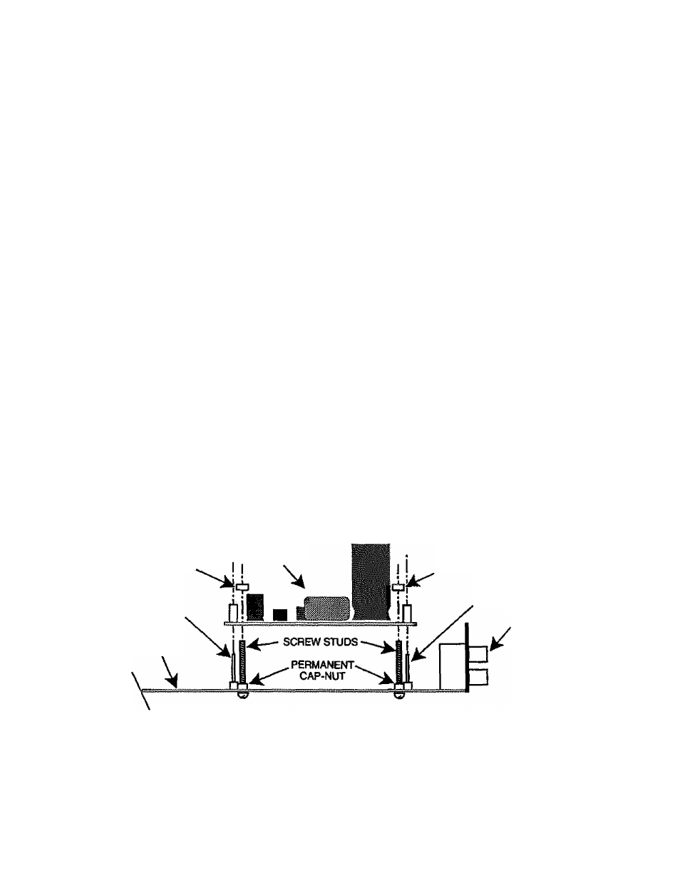
3. Remove the top cap-nut on each of the screw studs shown in figure below and position the PHO-802A board over the
two5-pinconnectorssothatthe corresponding Til and T12socketsand 5-pin connectors mate properly and the large
upright capacitors (black, 2200uF/16V) are positioned, as shown in figure below, nearest the RCA input jacks on the
rear panel of the GFP-345. You can use the screw studs as guides,
4. Press the PHO-802A board down firmly onto the two 5-pin connectors.
5. Screw the two cap-nuts, back onto the screw studs and firmly secure the nuts onto the PC8 with a 5,5mm nut-driver
or similar tool. Please note that the bottom cap-nuts must not be removed. The bottom cap-nuts secure the screw studs
to the main PCB and also act as spacers for the PHO-802A board. They are essential to prevent shorting between the
PHO-802A board and the main GFP-345 PCB.
6. Replace the top cover on the GFP-345 making certain all the screws are tightened securely to be sure that proper
shielding of the internal circuitry of the GFP-345 is effected.
7. There are two PHONO labels supplied with both the GFP-345 {in the plastic bag containing the instruction manual,
etc.), and also in the packaging of the PHO-802A board. Affix one PHONO label on the front panel over the AUX 1 label
at the INPUT O selector so that now it will read PHONO. The AUX 1 position is the maximum counterclockwise
position of the INPUT ® selector.
8. Affix the second PHONO label over the existing type above the RCA jacks on the rear panel which reads AUX 1 O so
that now it will read PHONO. Although this is not absolutely necessary, it will simplify identification of the now-PHONO
input to the GFP-345.
CAP-NUT.
5-PIN CONNECTOR
PHO-802A
CAP-NUT
GFP-345
MAIN PCB
5-PIN CONNECTOR
INPUT
SIGNALS
JACKS
10