Cabletron Systems Netlink FRX4000 User Manual
Page 4
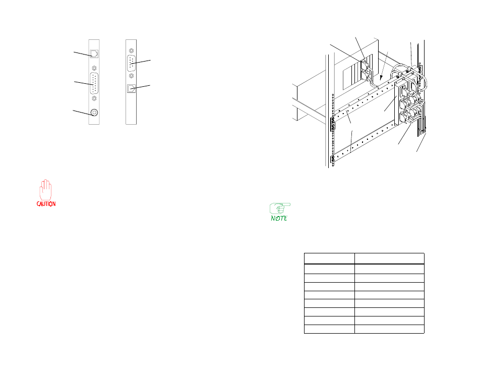
Figure 2
LAN Card Connectors
3. Assuming the node will be mounted in a rack, it can be secured to slides,
or set on a fixed or slide-out shelf. The node can also be mounted directly
to the cabinet frame, but this makes access difficult.
Do not support a rack-mounted node only in the front.
It must be supported at both front and rear.
4. Plug all cables into the appropriate connectors at the rear of the FRX6000,
and tighten the retaining screws on each cable connector that has them. (It
does not matter which end of an RLP cable plugs into the RLP.) Figure 1
shows the connectors on the rear of the chassis, and Figure 3 shows some
cable retaining screws.
5. Plug the RLP cables into their associated I/O boxes and tighten the
retaining screws. If the assembly is being rack mounted, attach the I/O
boxes and cables as shown in Figure 3, using the hardware provided.
Leave a 24–36 inch service loop in each cable between the mounting rails
and the rear of the node, to allow the unit to be pulled forward.
Installation & Setup Guide
3
Figure 3
Rack-Mounted I/O Boxes
In the above example, both Line Interface Cards (LICs) on the RLP
are 4-port LICs (V.35, RS-232, or RS-422). A T1 or E1 LIC includes
an RJ45 adapter instead of an RLP cable and I/O box. (The T1/E1
cable is not supplied.)
* One V.35 DTE cable is shipped as standard equipment with each FRX6000.
4
FRX6000
Token Ring
BNC
RJ45
RJ45
DB15F
Ethernet
DB9F
Table 1 WAN Port Interface Cables
Cable Type
Cabletron Part Number
V.35 DTE
FRX-V35DTE-CAB
1
V.35 DCE
FRX-V35DCE-CAB
RS-232 DTE
FRX-232DTE-CAB
RS-232 DCE
FRX-232DCE-CAB
RS-449 DTE
FRX-449DTE-CAB
RS-449 DCE
FRX-449DCE-CAB
X.21 DTE
FRX-X21DTE-CAB
X.21 DCE
FRX-X21DCE-CAB
Retaining Screw
RLP Cable
Support Rails
I/O Box
Cable Tie
Interface Cables
Service
Loop
Cable
Clamp