Section 4: unpacking instructions, Section 5: assembly instructions, Tools required for assembly – MTD 21A-340-100 User Manual
Page 5: Attaching the handle assembly
Attention! The text in this document has been recognized automatically. To view the original document, you can use the "Original mode".
SECTION 4: UNPACKING INSTRUCTIONS
1. Remove staples, break glue on top flaps, or cut
tape at carton end and peel along top flap to
open carton.
2. Remove loose parts included with unit (i.e.,
owner’s manual, etc.).
3. Cut along dotted lines and lay carton down flat.
All hardware required for assembly has been placed in position on the tiller.
4. Remove packing material.
5. Roll or slide unit out of carton. Check carton
thoroughly for loose parts.
6. Extend control cable and lay on the floor. Be
careful not to bend or kink control cable.
SECTION 5: ASSEMBLY INSTRUCTIONS
IMPORTANT:
This unit is shipped WITHOUT
GASOLINE OR OIL. After assembly, see separate
engine manual for proper fuel and engine oil
recommendations.
NOTE:
Right and left hand Is determined when
standing behind the tiller in the operating position.
TOOLS REQUIRED FOR ASSEMBLY:
(1) 1/2" Wrench or Socket*
(1) Pair of Pliers
(1) 3/8" Wrench*
*An adjustable wrench may be used.
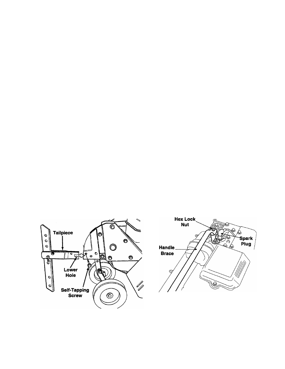
ATTACHING THE TAILPIECE AND DEPTH
STAKE
(See Figure 3)
Remove the two self-tapping screws on the frame.
Slide the tailpiece into the frame, with the lower hole
in the tailpiece toward the front. Secure with screws
just removed.
Figure 3
ATTACHING THE HANDLE ASSEMBLY
(See Figure 5)
1
.
2
.
3.
4.
Remove the hex bolt and cupped washer from
the top right side of the frame halves. Hold the
cable guide bracket on the left side of the frame
will fall when the bolt is removed. See Figure 5.
Insert the handle assembly between the two
frame halves. Insert hex bolt just removed
through the frame halves, handle assembly and
into the cable guide bracket (notch in cable
guide bracket goiss over the flange on the
frame). Tighten securely.
Loosen the hand knob which secures the handle
brace to the handle assembly.
Remove the hex lock nut from on top of the
engine, just to the left of the spark plug. See
Figure 4. Attach the curved end of the handle
brace to the top of the engine, using hex lock nut
just removed. Tighten securely.
5.
Figure 4
Select one of the three handle height positions
(three notches in v/elded bracket), and tighten
the hand knob to secure the handle in desired
position. Make cerliain carriage bolt is seated
securely into onis of the three positions
provided.