Assembly instructions, Handle assembly for models 113-892 and 902-033, Handle assembly for models 113-890 and 900-033 – MTD 113-892-033 User Manual
Page 4
Attention! The text in this document has been recognized automatically. To view the original document, you can use the "Original mode".
ASSEMBLY INSTRUCTIONS
HANDLE ASSEMBLY FOR MODELS 113-892 AND 902-033
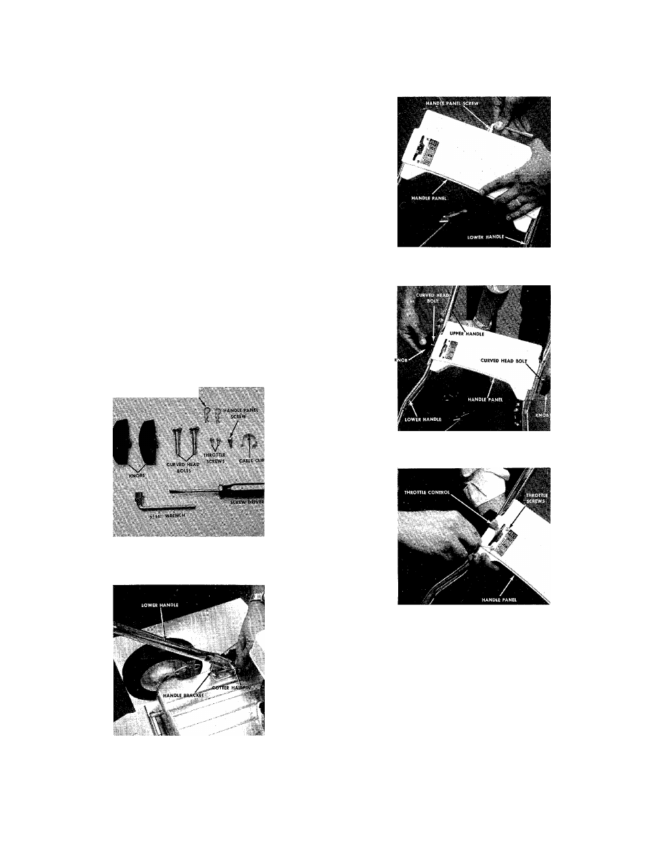
1.
Remove the loose hardware from the assembly
pack. You will need a screw driver and a 5/16"
wrench, either a socket as shown in figure 1 or an
open end wrench.
2. Assemble the lower handle to the handle brackets
as shown in figure 2.
3. Secure the handle with cotter hairpins on both
sides. See figure 2.
4.
Place the handle panel over the lower handle and
fasten with the handle panel screw using a 5/16"
wrench. See figure 3.
5. Place the upper handle over the lower handle and
line up the holes as shown in figure 4.
6. Insert the curved head bolt from the inside and
tighten the knob by hand. See figure 4.
7.
Place the throttle control in the handle panel and
assemble it with the two throttle srews using a
srew driver. See figure 5.
8. Use the cable clip to fasten the throttle control wire
to the lower handle.
COTTER HAIRPINS
FIGURE 1. LOOSE HARDWARE AND TOOLS
FIGURE 2. LOWER HANDLE ASSEMBLY
FIGURE 3. HANDLE PANEL ASSEMBLY
FIGURE 4. UPPER HANDLE ASSEMBLY
FIGURE 5. THROTTLE CONTROL ASSEMBLY
HANDLE ASSEMBLY FOR MODELS 113-890 AND 900-033
Your new mower is shipped completely assembled
with the exception of the handle and throttle control
assembly.
1.
Remove lawn mower and all parts from carton.
Make certain that all loose parts and literature are
removed from carton before carton is discarded.
2. Extend throttle control assembly, which is attached
to engine, to rear of mower and place on floor.
CAUTION: Do not bend or kink control wire.