MTD 310-300 User Manual
Page 2
Attention! The text in this document has been recognized automatically. To view the original document, you can use the "Original mode".
ASSEMBLY (See Figure 4)
Right hand (RH) and left hand (LH) are as observed
from the operating position.
1.
Assemble chrome handles to the frame with four hex
head cap screws 3/8—16 x 3/4 long and four lock-
washers 3/8”. DO NOT TIGHTEN.
2.
Assemble handle panel to the handles with four
carriage bolts 1/4—20 x 1-1/2 long and hex locknuts
1/4—20 thread. Assemble handle panel so you can
read the instructions on the handle panel from the
operating
position.
LIFT
HANDLE
UP
AS
YOU
TIGHTEN
ALL
BOLTS
AND
NUTS
ON
THE
HANDLE ASSEMBLY.
3.
The linkage arm for the transmission is located on
the RH side of the frame. Pull the arm back into
reverse. (Towards the operator.) If maybe necessary
to roll the snow thrower slightly until it engages in
the reverse position. Assemble the ferrule to the shift
lever handle use hole marked “21” on the handle panel
and screw in the shifting rod. Adjust the rod by screw
ing it in or out until it fits into the linkage arm on
the side of the frame. Secure it with a cotter pin.
4.
Chute Crank.
Assemble the chute crank (longest rod)
into the two holes in the handle panel being sure the
rod passes through the lock bracket. It may be
necessary to loosen the black knob on the handle
panel. Push the rod all the way through and assemble
it to the universal joint with a cotte pin.
5.
Remove the wing nut, washer and c a r r i a g e bolt
5/16—18 X 5/8 long from the chute assembly. Lift
the deflector and reassemble. If the deflector will
not move loosen the screw and nut slightly so it
pivot freely.
6.
Attach the drift cutters to each side as shown on the
parts drawing.
CONTROLS
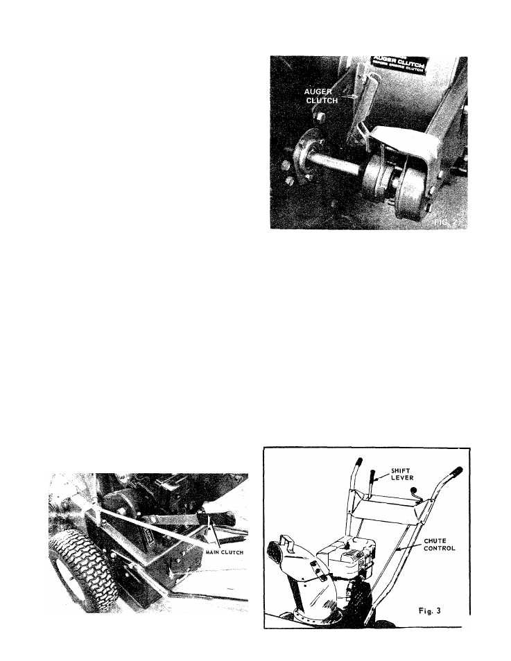
Main Clutch.
This clutch shuts off the power to the
wheels and auger. When the handle is up it is in the
disengaged position. Always shut off the main clutch
when engaging and disengaging the auger clutch. It is
shown in the disengaged position in the photo.
(See Figure 1)
Auger Clutch
is located on the right hand side of the
frame just behind the thrower housing. The clutch is
shown in the disengaged position.
When the handle is up the auger is disengaged. Do not
engage or disengage the clutch without disengaging the
main clutch. Disengaging the auger clutch allows you
to drive the snow thrower to and frqm the work area
without the auger turning. (See
Figure 2).
It is not necessary to disengage auger clutch when start
ing.
CAUTION—Main
clutch
must
he
disengaged
when
starting.
Shift Lever.
Move the shift lever into either forward or
reverse rapidly. Engaging slowly causes wear on the
clutch collars. There is no clutch to engage the drive
wheels.
To stop the snow thrower move the shift lever into
neutral (N). Move this control only when the engine is
operating.
(See Figures/
Chute Controls.
Release the lock and turn the crank to
rotate the chute. Loosen the wing nut to adjust the
deflector.
(See Figure 3)
FIG. 1
FORM NO. 770-2837B