Adjustments, To stop engine and blade, Using your rotary mower – MTD 11-096R000 User Manual
Page 8: Cutting height adjustment, Throttle control adjustment
Attention! The text in this document has been recognized automatically. To view the original document, you can use the "Original mode".
ADJUSTMENTS
TO STOP ENGINE AND BLADE
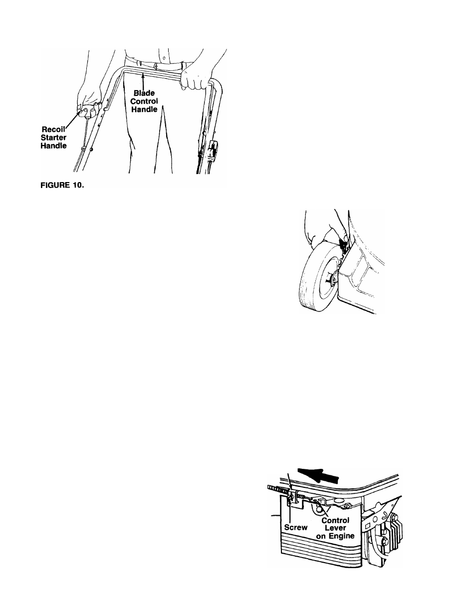
1. Release the blade control handle to stop the
engine and blade.
A
WARNING: The blade continues to rotate
for a few seconds after the engine i s shut
off.
2. Disconnect the spark plug wire and ground it
against the engine to prevent accidental starting
while equipment is unattended.
USING YOUR ROTARY MOWER
Be sure that lawn is clear of stones, sticks, wire, c r other
objects which could damage lawn mower or e ngine.
Such objects could be accidently thrown by the -power
in any direction and cause serious personal injury to
the operator and others.
For the best results, do not cut wet grass because it
tends to stick to the underside of the mower, pi event
ing proper mulching of grass clippings. In addition, wet
grass could cause you to slip and fall. New grass;, thick
grass or wet grass may require a narrower cut.
For best results, cut off one-third or less of the total
length of the grass. Lawn should be cut in the fall as
long as there is growth.
This mower is designed to be operated at full ihrottle
to give you the best cut and do the most effective job
of mulching.
A
WARNING: If you strike a foreign cibject,
stop the engine. Remove wire from spark
plug, thoroughly inspect the mower 1 or any
damage, and repair the damage before
restarting and operating the mower. Exten
sive vibration of the mower during opera
tion is an indication of damage. Tf e unit
A
WARNING: Do not at any time make any
adjustment to iawn mower without first
stopping engine and disconnecting spark
plug wire.
CUTTING HEIGHT ADJUSTMENT
An adjusting plate and thumb lever at each wheel posi
tion provides cutting height adjustment. Each adjusting
plate has nine height positions. Height of cut will be
changed when the thumb lever Is moved from one hole
to another. Simply depress the lever towards wheel and
move wheel and lever assembly to desired position. All
wheels must be placed In the same relative position.
See figure 11.
FIGURE 11.
THROTTLE CONTROL ADJUSTMENT
If the throttle control requires adjustment or has been
replaced, adjust as follows.
1. Remove the screw shown in figure 12. Remove the
cable clamp from the cable.
2. Push the throttle control lever on the handle all the
way forward to CHOKE or START position. Make
certain the throttle control lever remains in this
position.
3. Push the control lever on the engine as far toward
the
rear
of the engine as it will go. Secure the cable
in this position with the cable clamp and screw.
Cable
Clamp,
should be
repaired.
promptly inspectée and
FIGURE 12A.—Briggs & Stratton Quantum Engine