Figure 6, Attaching the starter rope (hardware c), Instalution of front hub caps (optional) – MTD 111-508R000 User Manual
Page 7: Final assembly of mower
Attention! The text in this document has been recognized automatically. To view the original document, you can use the "Original mode".
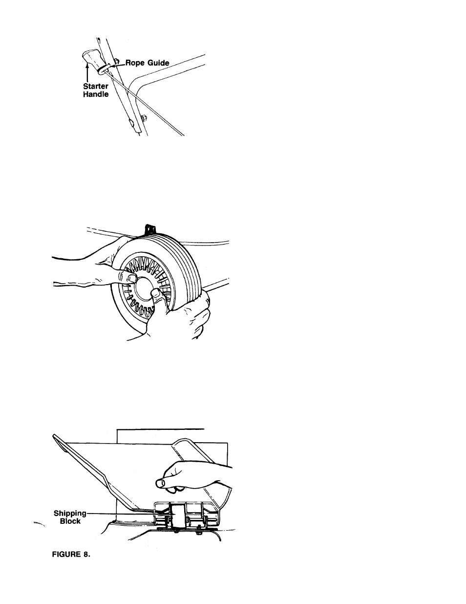
FIGURE 6.
ATTACHING THE STARTER ROPE (Hardware C)
1. The starter rope is inside the top of the engine. Ad
ditional rope may be wound around the starter han
dle. If so, unwind the rope from the handle.
With
the
spark
plug
wire
disconnected
and
grounded, depress the blade control handle and
pull the rope out of the engine.
Place the rope guide around the starter handle, so
-the rope guide is positioned as shown in figure 6
(bends downward slightly). Insert the rope guide
through the side of the upper handle, and secure
with hex lock nut.
2
.
3.
FIGURE 7.—Optional Hub Caps
INSTALUTION OF FRONT HUB CAPS (Optional)
1.
If your mower is equipped with hub caps which
have four tabs, line up the tabs on the hub caps
with the holes in the wheels. Push to lock in
position.
2. If your mower is equipped with 2" wide tires, place
hub caps in position against the inner hub of the
wheel. Press firmly around the center portion of
hub cap in a circular motion, similar to installing
------- a lid on a round, plastic container. See figure 7.
The hub caps are flexible and will snap over the
3
V
2
" diameter wheel hubs.
NOTE: It may be helpful to place the hub caps in hot
tap water for several minutes to make them pliable
before installing, especially if the temperature is less
than 60°F.
FINAL ASSEMBLY OF MOWER
1. The chute deflector on your mower is held in an
upright position by a block for shipping purposes
only. This shipping block must be removed and
discarded before the mower is put into operation.
------- See figure 8.
To remove the shipping block, move the spring-
loaded chute toward the engine by pushing above
the shipping block. Remove the block and carefully
lower the chute into operating position, keeping
fingers out of the way.
2.
Make certain all nuts and bolts are tightened
securely.