MTD 214-200A User Manual
Page 10
Attention! The text in this document has been recognized automatically. To view the original document, you can use the "Original mode".
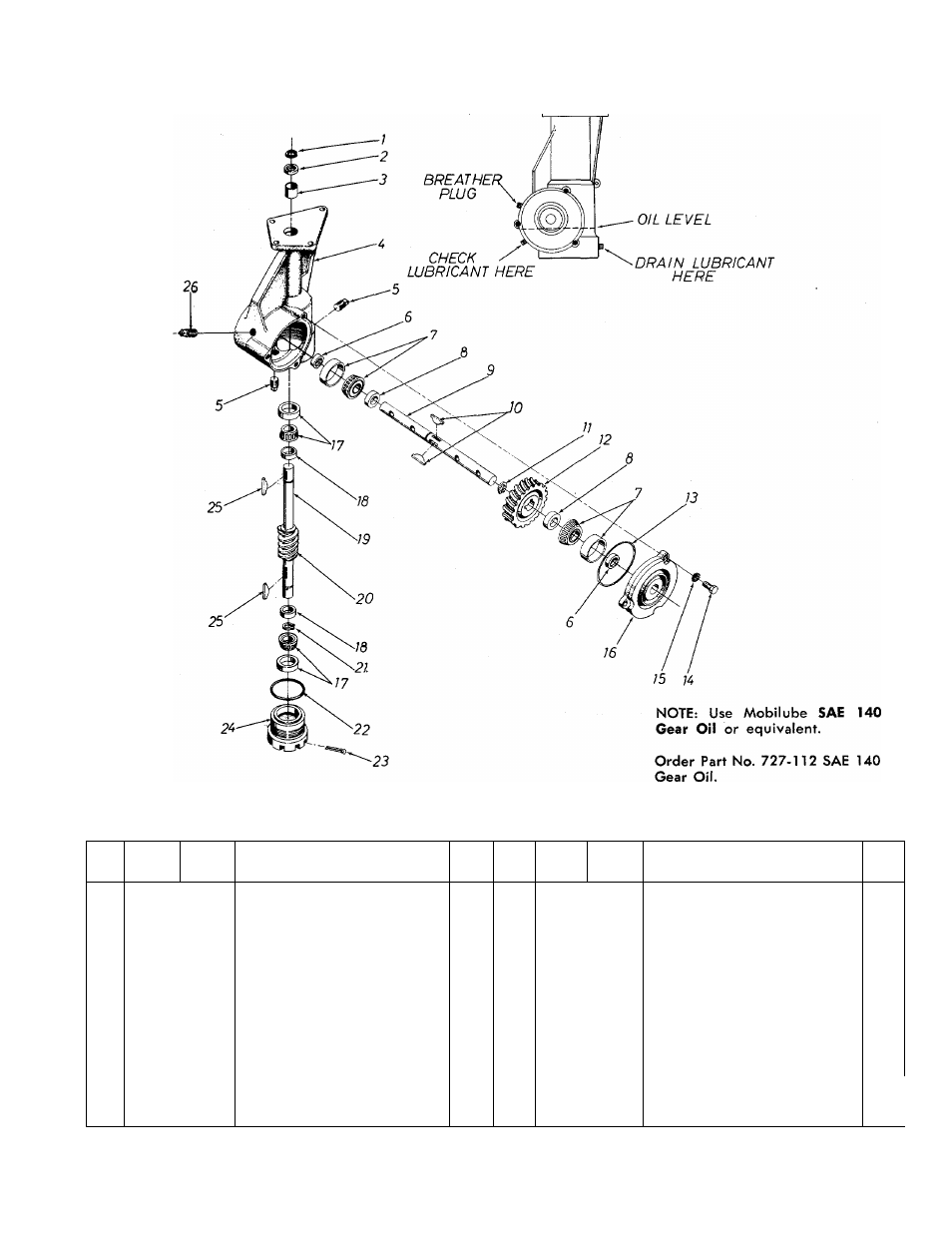
GEAR CASE ASSEMBLY 4500
Maintain with five (5) ounces of lubricant.
PARTS LIST FOR GEAR CASE ASSEMBLY 4500
REF.
NO.
PART
NO.
COLOR
CODE
DESCRIPTION
NEW
PART
REF.
NO.
PART
NO.
COLOR
CODE
DESCRIPTION
NEW
PART
1
716-119
Snap Ring %" Dia. Shaft
14
710-371
Hex Scr. 5/16-18
X.88
" Lg.
2
721-100
Oil Seal %" Shaft
15
736-119
L-Wash. 5/16" Scr.*
3
748-106
Sleeve Bearing .752" l.D.
16
717-227
Bearing Cap—Bolton Type
4
717-226
Gear Case
17
741-107
Roller Bearing %" Bore
5
737-103
Sq. Hd. Pipe Plug %" Thd.
18
711-469
Spacer .755" l.D. x 1.265" O.D
6
721-102
Oil Seal Double Lip 1" Shaft
19
738-171
Worm Shaft
7
741-108
Roller Bearing 1" Bore
20
717-167
Worm
8
711-131
Spacer 1.005" l.D. x 1.390"
21
716-101
Snap Ring for .750" Dia. Shaft
O.D.
22
735-100
O-Ring 2.12x2.38
9
711-133
Tine Shaft
23
714-474
Cotter Pin
Va"
Dia. x .75" Lg.*
10
714-103
#91 Woodruff Key
V
a
"
x
%"
24
10538
Bearing Adjustment Cap
Dia.
25
714-126
#9 Hi-Pro Key 3/16
X
%" Dia.
11
716-102
Snap Ring for 1.00" Dia. Shaft
26
737-102
Sq. Hd. Pipe Plug with Vent
12
717-105
Worm Wheel
%" Thd.
13
735-101
O-Ring 3.62 X 3.88
____
*for
faster service, obtain standard nuts, bolts and washers locally. If these items cannot
be obtained locally, order by part number and size, as shown on parts list.
10