Assembly instructions, Unpacking, Ahaching the lower handle (hardware a) – MTD 111-080R000 THRU 111-089R000 User Manual
Page 5: Attaching the upper handle (hardware b)
Attention! The text in this document has been recognized automatically. To view the original document, you can use the "Original mode".
ASSEMBLY INSTRUCTIONS
This owner’s guide covers various modeis of
mowers. Foiiow only those instructions which per
tain to your unit.
IMPORTANT: This unit is shipped WITHOUT
GASOLINE or OIL. After assembly, service engine
with gasoline and oil as instructed in the separate
engine manual packed with your unit.
NOTE: Reference to right or left hand side of the
mower is observed from the operating position.
Tools Required for Assembly
(1) Pair of Pliers
(1) 1/2" Wrench*
(2) 7/16" Wrenches*
*Or two 6" Adjustable Wrenches
Lower
Handle
Handle
Mounting
Bracket
Hairpin
Clip
FIGURE 1.
Hole in Blade
Control Handle
3.
4.
UNPACKING
1. Remove the lawn mower from the carton by open
ing the top flaps and lifting the unit out. Be careful
of the staples. Make certain all parts and literature
have been removed from the carton before the car
ton is discarded.
2. Disconnect the spark plug wire and move away
from the spark plug.
Stretch out all control cables and place on the floor.
Be careful not to bend or kink the cables at any
time during assembly.
Remove page four from this manual and lay the
contents of the hardware pack on the illustration
for identification.
AHACHING THE LOWER HANDLE (Hardware A)
1. Attach the lower handle by placing the bottom
holes in the lower handle over the weld pins on the
handle mounting brackets extending through the
rear of the deck.
Using a pair of pliers, squeeze one leg of the lower
handle against the handle mounting bracket. In
sert the hairpin clip into the
inner
hole on the weld
pin. See figure 1. Repeat on other side.
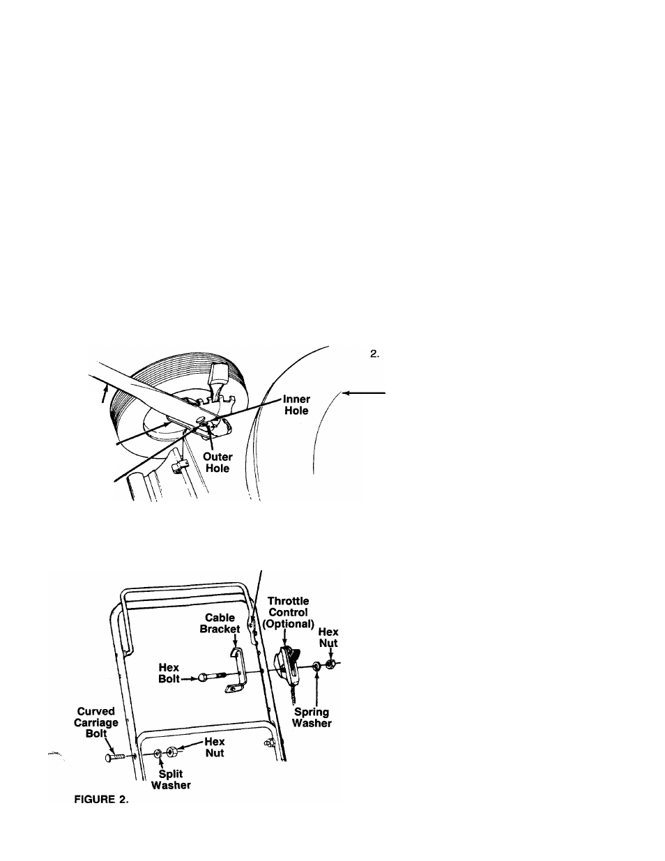
NOTE: There are two (2) holes in the handle mounting
brackets. Place the hairpin clip in the inner hole for
operation. Outer hole is for storage.
ATTACHING THE UPPER HANDLE (Hardware B)
1. Place the upper handle in position over the lower
handle. The hole in the side of the blade control
handle (attached to the upper handle) must be on
the
left
side.
2
. Secure the upper handle to the lower handle us
ing the curved head bolts, split washers and hex
nuts as shown in figure 2.
AHACHING THE CABLE BRACKET AND
THRDTTLE CDNTRDL (Hardware D) (Dptional)
If your mower is equipped with a remote throttle con
trol, it is already attached to the engine. Attach the
cable bracket and throttle control to the
left
side of up
per handle as follows. See figure 2.
NOTE: If your mower does not have a remote throttle
control, attach the cable bracket using the 1" long hex
bolt provided and following steps 2 and 4 only.
1. Route the throttle control cable inside the handle
mounting bracket and beneath the lower handle.
Place cable bracket against left side of upper han
dle, lining up the hole in the bracket with the bot
tom hole in upper handle. Place 1/4" hex bolt
through cable bracket and handle, from the inside
to the outside.
Place throttle control on the hex bolt (outside of
the upper handle), with the throttle lever facing
upward.
2
.
3.