Unpacking and set-up – MTD Yard-Man 7090-1 User Manual
Page 4
Attention! The text in this document has been recognized automatically. To view the original document, you can use the "Original mode".
THREADED ROD
HANDLE PANEL
MASTER CLUTCH LEVER
CHUTE
ADJUSTMENT
SHAFT
MASTER CLUTCH ROD
LOWER CLUTCH ARM
UNIVERSAL JOINT
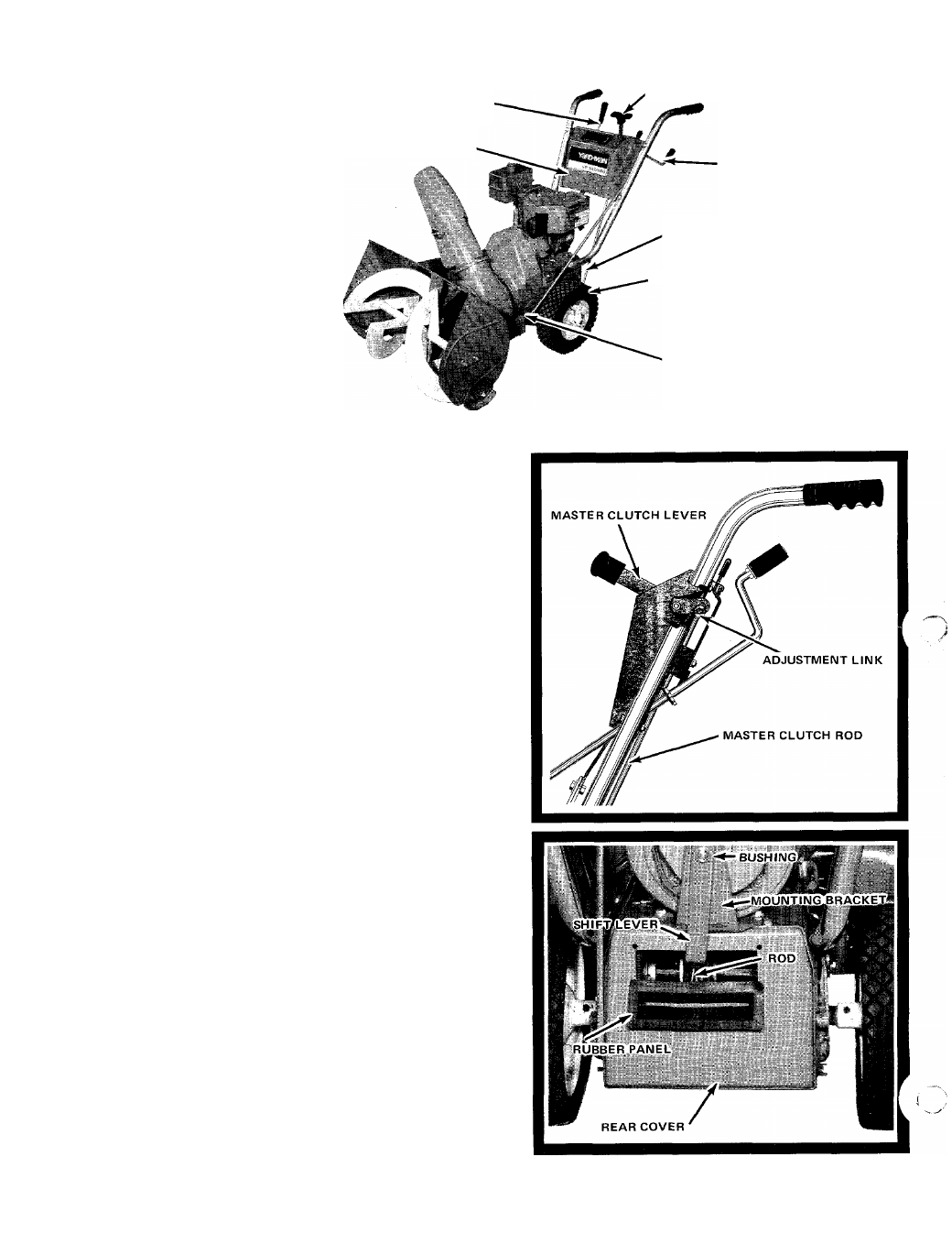
UNPACKING AND SET-UP
1. Be sure carton is right side up, cut end panels out and
fold flat on floor. Remove inner pack and roll unit out
of carton.
2. Assemble right and left handle tubes to the unit with
bolts and flat washers. Do not tighten.
3. Assemble handle panel assembly to the under side of
right and left handle tubes and secure with four slotted
hex head bolts and lock nuts. Tighten all bolts on the
handle assembly. Place handle grips over ends of the
handle tubes.
4. Assemble chute adjustment shaft through hole in the
handle panel and into universal joint located on left
hand side of the frame. Align hole in universal joint with
the hole in chute adjustment shaft and drive spring pin
through the holes.
5. Attach master clutch rod adjusting link into the bottom
hole of master clutch control located on the handle
panel and attach rod end into hole in lower clutch arm.
Secure with cotter pins and spread. Move master clutch
lever forward to the end of the notch. To adjust, remove
cotter pin from clutch lever adjustment link and thread
up or down until the link is the full hole short of reach
ing the hole in the clutch lever. Move clutch lever back
slightly to reconnect link. Replace cotter pin and spread.
6. Remove rubber shift lever panel from parts package and
slip over end of shifting lever. Insert shifting lever into
back of rear cover and slip small shifting rod through
bushing in end of lever. Secure shift lever to mounting
bracket with bolt, washer, bushing, and nut. Assemble
threaded rod into end of shift lever through handle
panel, locking rod in position with nut. Assemble plastic
knob onto shift lever rod. Snap rubber shift lever panel
into rear frame cover holes. Refer to Page 7 to make
adjustment of shift lever panel notches.