MTD 114-100A User Manual
Page 3
Attention! The text in this document has been recognized automatically. To view the original document, you can use the "Original mode".
CAUTION
ASSEMBLY FOR OPTIONAL HANDLE
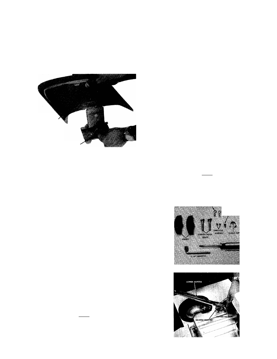
Please note that the chute deflector on
your mower is in an upright position,
it is held in that position by a shipping
block. This block is used for shipping
purposes only. It must be removed and
discarded before your mower is put
into operation.
Chüte Deflector
Shipping Block to be Removed
HANDLE ASSEMBLY
1.
Remove the loose hardware from the assembly
pack. You will need a screwdriver and a 5/16"
wrench, either a socket as shown in figure 2 or an
open end wrench.
2. Assemble the lower handle to the handle brackets
as shown in figure 3.
3. Secure the handle with cotter hairpins on both sides.
See figure 3.
4.
Place the handle panel over the lower handle and
fasten with the handle panel screw using a 5/16"
wrench. See figure 4.
5. Place the upper handle over the lower handle and
line up the holes as shown in figure 5..
6.
Insert the curved head bolt from the inside and
tighten the knob by hand. See figure 5.
7. Place the throttle control in the handle panel and
assemble it with the two throttle screws using a
screwdriver. See figure 6.
Your new mower is shipped completely assembled
with the exception of the handle and throttle control
assembly.
1.
Remove lawn mower and all parts from carton.
Make certain that all loose parts and literature are
removed from carton before carton is discarded.
2. Extend throttle control assembly, which is attached
to engine, to rear of mower and place on floor.
CAUTION: Do not bend or kink control wire.
3. Assemble upper handle to lower handle using four
each screws and locknuts provided in parts bag.
4.
Assemble complete handle assembly to mower.
Holes at bottom of lower handle are to be fitted
over studs located in handle mounting brackets.
5.
Position throttle control assembly on right hand
side of upper handle so that holes in control as
sembly and handle are in line. Secure in place with
screw and locknut found in parts bag. Secure throt
tle wire to lower right handle tube with clips in
parts bag.
6. Place the plastic control cover over the throttle con
trol and secure with two self-tapping screws.
7. Check all nuts and bolts for correct tightness.
NOTE
It may be necessary to bend the ends
of the lower handle inward slightly to
assure a snug fit against the deck
mounting area.
8. Use the cable clip to fasten the throttle control wire
to the lower handle.
NOTE
It may be necessary to spread the ends
of the lower handle outward slightly
to assure a snug fit against the bracket
mounting area.
COnER HAIRPINS
HANDLE PANEL
SCREW
FIGURE 2. LOOSE HARDWARE AND TOOLS
FIGURE 3. LOWER HANDLE ASSEMBLY