Service notes, Drive belt slips, Reverse drive wheel adjustment – MTD 219-360 User Manual
Page 6: Adjustments - (see fig. 4), To check, To adjust
Attention! The text in this document has been recognized automatically. To view the original document, you can use the "Original mode".
SERVICE NOTES
DRIVE BELT SLIPS
1.
Lubricate contact surface between pivot bracket
assembly and adjustment plate.
2. Check pivot bracket assembly locknuts for excessive
tightness.
3. Check control rod for improper assembly. If adjust
ment tube is attached to lower end instead of upper
end, it may bind on control lever and prevent full
use of tension spring.
4.
If spring tension is still insufficient, adjust to
another mounting hole on control lever.
5. Some measure of belt adjustment may be made by
loosening the mounting bolts on the adjustment plate
and moving as needed. This adjustment is usually
used for reverse drive wheel adjustments.
6. Large pulley and belt may be rubbing on lower belt
guard,
7. Idler pulley must operate freely.
8. Belt guard or clips must not touch the belt when it
is tightened.
REVERSE DRIVE WHEEL ADJUSTMENT
1. Reverse drive wheel should line up with its matching
pulley. If it does not, loosen pulley to which revers
ing drive wheel is attached and align as needed.
When reassembling, tighten set screw securely.
2. Matching pulley for reversing drive wheel can be
mounted one way only. The reversing drive wheel
must operate in the deeper groove.
3. If belt retainer touches engine pulley after adjust
ment, move to outside mounting or bend away as
needed.
4.
Additional reverse adjustment may be made by
loosening the mounting bolts on the adjustment plate
and moving as needed.
5. Reverse should operate only when control handle
assembly is held in reverse position. Adjust control
rod for proper operating position.
NOTE: If belts are excessively stretched, replacement
will be necessary.
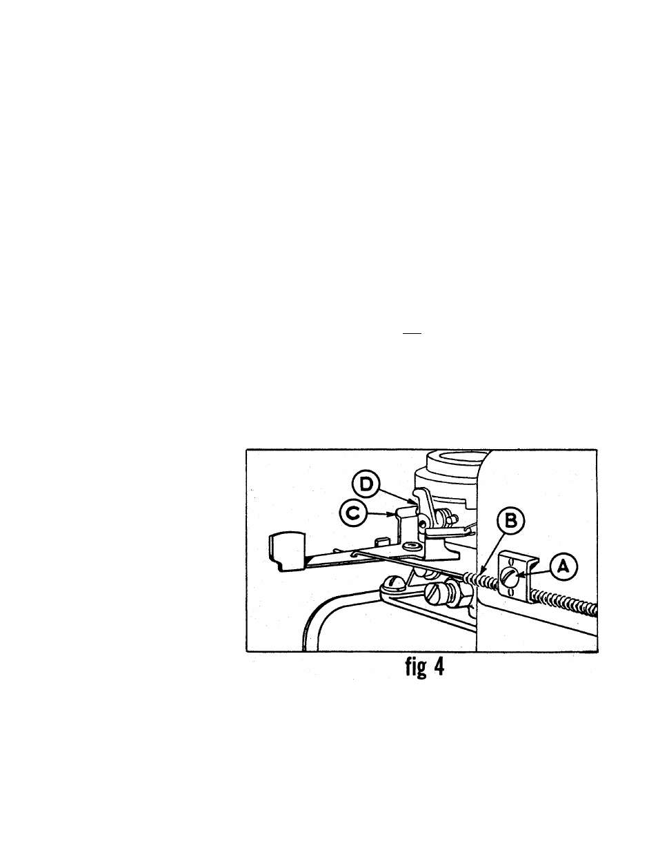
ADJUSTMENTS - (see fig. 4)
To Check:
Remove Air Cleaner. Move Throttle
Assembly to CHOKE position. The
carburetor
choke should then be
closed. Move the Throttle to STOP.
Control lever on carburetor should
then make good contact with stop
switch to short out ignition.
To Adjust:
Place Throttle on equipment in FAST
(high speed) position. Lever “C” on
carburetor should be just touching
choke arm at “D”. To adjust, loosen
casing clamp screw “A” on blower
housing. Move control casing ”B”
forward or backward until correct
position is obtained. Tighten screw
“A”. Recheck above operation and
replace Air Cleaner.
NOTE:
This instruction manual covers various models and all'accessories
shown do not necessarily apply to your model tiller.
MT-D PRODUCTS INC extends its warranty only on
the tiller. If repairs or service is needed on the engine,
please contact your nearest, authorized engine service
outlet. Check tiie “Yellow Pages” of your telephone
book under “Engines — Gasoline.”
Find It Fast
In Th*
'Yellow Pages'
FORM NO.770-1884H
PRINTED IN U.S.A.